
Compressed air vehicle screen clearing system

a compressed air and vehicle screen technology, applied in vehicle cleaning, vehicle maintenance, cleaning equipment, etc., can solve the problems of dredging device not considering a compressed air tank and individual nozzles that are operably controlled by the user, device not anticipating a powered air compressor, and introducing considerable drag on the engin

Inactive Publication Date: 2019-11-12
DAVIS KENNETH +1
View PDF6 Cites 0 Cited by
  • Summary
  • Abstract
  • Description
  • Claims
  • Application Information

AI Technical Summary

Benefits of technology

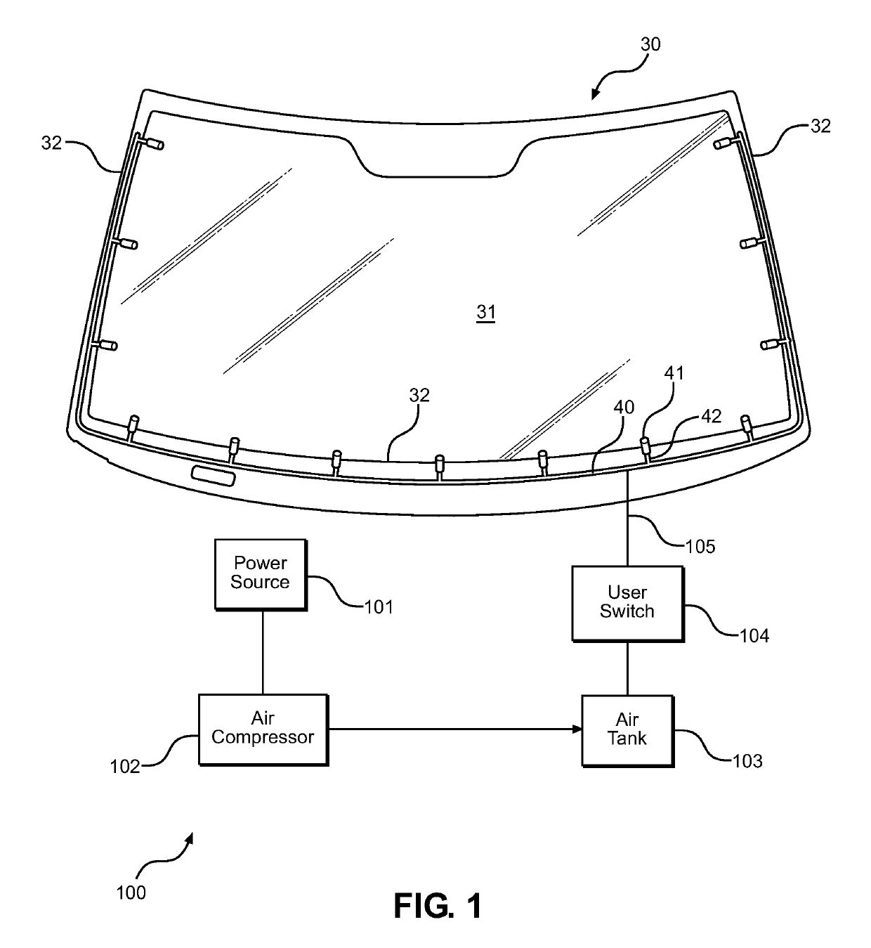
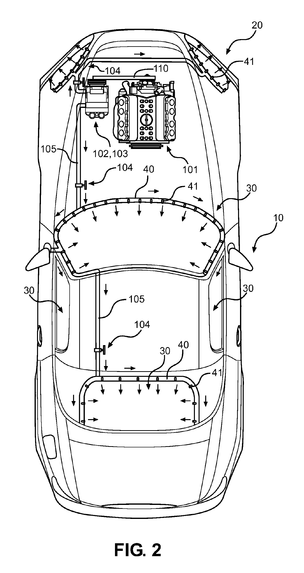
[0022]Another object of the present invention is to provide a vehicle screen clearing system that routes a network of air lines through a vehicle for the placement of nozzles around the perimeter of the automotive glass and for the operative location of valves that allow for independent control over the operation of specific nozzle sets based on the set positioning around a vehicle.
[0024]Another object of the present invention is to provide a vehicle screen clearing system that is ideally suited for use in automotive or similar land vehicle use, wherein the system may assist existing wiper blades or act as a complete replacement thereof.
[0026]A final object of the present invention is to provide a vehicle screen clearing system that utilizes compressed air that is of sufficient pressure to forcibly remove water droplets and light debris from a windshield or windscreen without requiring excessive vehicle power to drive the system compressor.

Problems solved by technology

While serving a similar purpose, this system introduces considerable drag on the engine and is less efficient than the electrical system of the present invention.
Similar to the other devices of the art, the Drews device fails to contemplate a compressed air tank and individual nozzles that are operably controlled by the user.
These devices fail to anticipate a powered air compressor, being a piston or rotary compressor and powered by electric or pulley driven power, whereby a tank of compressed air is maintained on the vehicle for use in ejecting pressurized air over the vehicle windshield on demand by a user.
The devices of the prior art also fail to disclose such a use in conjunction with a motorcycle helmet, wherein a rider is assisted in clearing the exterior surface of his or her windscreen while riding in foul weather.

Method used


Image

  • Compressed air vehicle screen clearing system
  • Compressed air vehicle screen clearing system
  • Compressed air vehicle screen clearing system

Examples


Embodiment Construction

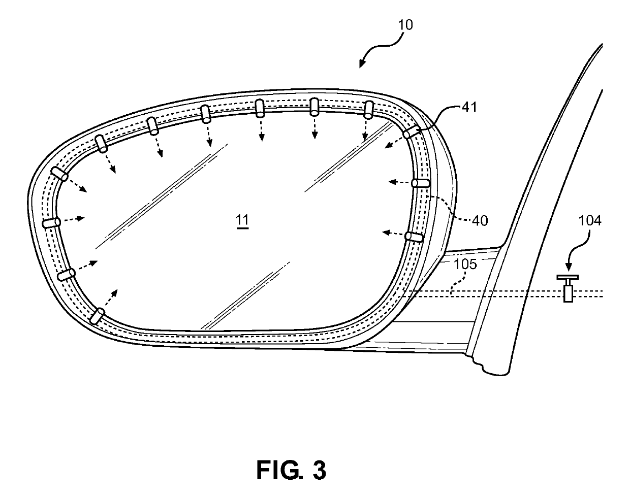
[0033]Reference is made herein to the attached drawings. Like reference numerals are used throughout the drawings to depict like or similar elements of the vehicle screen clearing system. For the purposes of presenting a brief and clear description of the present invention, the preferred embodiment will be discussed as used for increasing the air pressure over automotive glass and motorcycle helmet windscreens for operably and forcibly removing water droplets and debris therefrom without resorting to physical removal tools. The figures are intended for representative purposes only and should not be considered to be limiting in any respect.

[0034]Referring now to FIG. 1, there is shown the present system deployed on vehicle glass 30, notably the windshield of an automobile. Also illustrated are the system elements of the present invention. The system provides an alternative or replacement means of clearing the glass surface 31 of a vehicle using high compressed air and nozzles 41 disp...


PUM


Abstract

A compressed air system is provided for automotive or motorcycle use, wherein compressed air is utilized to assist clearing a windshield or a windscreen during foul weather. The system comprises an electrically driven or belt driven air compressor, a compressed air reservoir tank, a network of air lines throughout the vehicle or attached to a rider's helmet, and a plurality of air nozzles that release the air from the air lines on command. The ejected air is highly pressurized and exits at a high velocity to remove water droplets and particles for improved clarity through the windshield or wind screen. A user-operated switch controls at least one valve to release the compressed air from the network of air lines and through the nozzles, wherein the compressed air tank is continually replenished to allow for consistent and repeated bursts of compressed air over an extended period.

Description

CROSS REFERENCE TO RELATED APPLICATION[0001]This application claims the benefit of U.S. Provisional Application No. 61 / 720,739 filed on Oct. 31, 2012, entitled “The Wipeless Windshield for On and Off-Road Vehicles.” The above identified patent application is herein incorporated by reference in its entirety to provide continuity of disclosure.BACKGROUND OF THE INVENTION[0002]Field of the Invention[0003]The present invention relates to a compressed air system for the windshield of a land vehicle or the helmet of a motorcycle rider that increases the air pressure thereon for forcible removal of water droplets and debris therefrom. The system is contemplated for use with automotive windshields, side windows, and rear windows, while an embodiment further contemplates use with a motorcycle helmet face shield.[0004]Driving in foul weather can be dangerous for motorists in traffic and in dimly lit areas. Water droplets and debris from the road can accumulate on the windshield of the vehicle...

Claims


Application Information

Patent Timeline
Patent Type & Authority Patents(United States)
IPC IPC(8): B60S1/54H01L21/67A42B3/26B60S1/56B60S1/58B60S1/60B60R1/06A47L1/02
CPCB60S1/56B60R1/0602B60S1/54A42B3/26B60S1/60B60S1/58H01L21/67028
Inventor DAVIS, KENNETHCOLLINS, JR., GREGORY
Owner DAVIS KENNETH
Learn More