Electric machine

a technology of electric machines and motors, applied in the direction of windings, mechanical energy handling, association with control/drive circuits, etc., can solve the problems of design function but not optimal, and achieve the effects of high efficiency, high performance and specific power

Active Publication Date: 2019-11-12
LIMANSKIY VALENTIN GRIGORYEVICH
View PDF6 Cites 0 Cited by
  • Summary
  • Abstract
  • Description
  • Claims
  • Application Information

AI Technical Summary

Benefits of technology

[0006]The purpose of the invention described herein is to create a high-performance, convenient-to-operate and environmentally friendly device with high efficiency and specific power to generate electric and / or mechanical energy, to convert electric energy into mechanical energy and vice versa, etc. Thus, the objective of the invention is to expand the area of application, to reduce costs and to increase the specific power and efficiency of the electric machines. Depending on the application, this electric machine may be used as an electric motor, a power generator, an electric motor-generator; in particular, it may be used as an electric DC transformer, wherein an electric motor fed by an alternating electric current rotates an electric generator that feeds direct electric current into an external two-wire grid (or vice versa).
[0011]With a sufficient number of stator coils, one may use the control device to achieve specific changes of the stator magnetic field (for example, achieve a rotation of the stator magnetic field) and make the magnetized rotor core perform a required motion (for example, revolve about its axis). In particular, the stator magnetic field can be rotated depending on the spatial position and the magnetic condition of the rotor that performs rotating (see ibid., pp. 313-314), or reciprocating motions. By generating, at each point in time, a predetermined (corresponding) stator magnetic field in an electric machine (thus making the rotor perform a predetermined motion), control systems may manage the operation of machinery, gear, vehicles, etc. (see ibid., pp. 5-6, 369-370, 389). Therefore, chain control opens a very broad range of rotor motion control possibilities in an electric machine, such as: rotating (including with variable frequency), reciprocating (including with variable frequency), frequent starts and stops, intermittent motion, back-and-forth rotation, retention of the rotor at a given angular direction, etc. Thus, the electric machine described herein is multifunctional and can be designed in different variations.
[0012]If the proposed device is used as an electric motor, it shall have the following distinct features: firstly, an enhanced concentration of the magnetic flux of the stator core (due to the radial width of the stator core) in the rotor of the electric machine; secondly, a lower energy consumption to perform the rotation of the stator magnetic field (as the stator coils switched at each point in time are relatively small); and thirdly, a significant relative decrease in anti-induction in the stator winding because the length of the stator magnetic line (excited by the rotor in the stator core) exceeds the length of the rotor magnetic line (excited by the stator in the rotor core).
[0013]If the proposed device is used as an electric generator, it shall have a significant relative increase of induction in the stator winding, for example, due to the use of a rotor with two beveled poles, which reduces the energy consumed to rotate the rotor. For example, in those rotor points where magnetic force lines of the rotor and the stator are approximately parallel, there is no significant deceleration of the rotor which can be rotated, for example, by an electric motor (an important system consisting of two interacting electric units: electric motor and electric generator shall hereinafter be referred to as electric motor-generator). Thus, the proposed electric machine has asymmetric magnetic interaction of the rotor and the stator.
[0016]The previously mentioned novelty of the device achieves a significant increase of specific power and efficiency of the electric machine and enables it to have a wide range of applications in the economy.

Problems solved by technology

Evidently, such a design does function, but is not optimal: not all the coils operate at full capacity at any moment.

Method used


Image

  • Electric machine
  • Electric machine
  • Electric machine

Examples


example 1

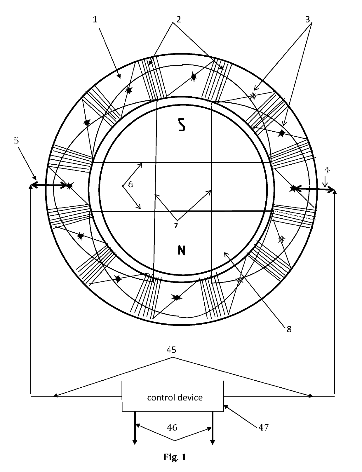
[0029]FIG. 1 depicts an end view of the magnetic system of a DC electric motor, or DC power generator which consists of the magnetically soft core of the stator (1) with tangential, connected in series stator winding coils (2), their electrical terminals (3), and a control device (47) with terminals / wires (45), which, at each point in time connects an external two-wire grid (46), via electric contacts (4) and (5), with the specified, connected in series, tangential coils (2) of the stator winding. At subsequent times, the control device selects new terminal / wires that connect the external two-wire grid with new contacts of the stator coil. In this case, force lines (6) and (7) of the magnetic field of the stator (1) and the rotor (8) penetrate the core of a two-pole rotor (8) and have an almost stable relative orientation during the rotation of the rotor (8) (approximately mutually perpendicular), which ensures a torque stability of the rotor (8) under a steady load.

[0030]In this el...

example 2

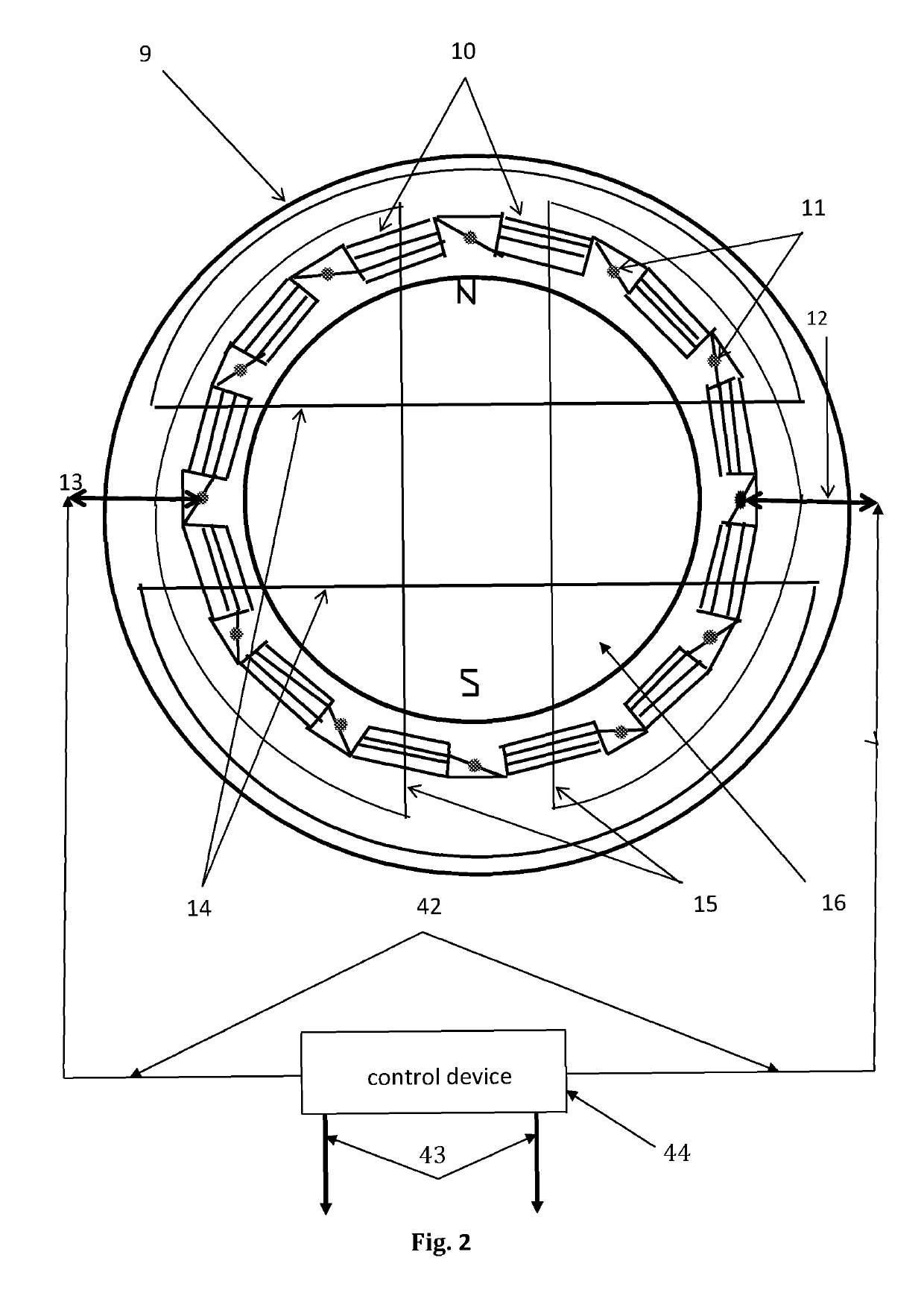
[0032]FIG. 2 shows an end view of the magnetic system of a DC electric motor, or DC electric generator, which consists of the magnetically soft core of the stator (9) with radial, connected in series stator winding coils (10), their electrical terminals—contacts (11), and a control device (44) with terminals / wires (42), which at any point in time connects an external two-wire grid (46) via electric contacts (12) and (13), with the specified, radial stator coils (10) connected in series. At subsequent times, the control device selects new terminal / wires that connect the external two-wire grid with new contacts of the stator coil. In this case, power lines (14) and (15) of the magnetic field of the stator (9) and the rotor (16) penetrate the core of a double-pole rotor (16) and have an almost stable relative orientation during the rotation of the rotor (16) (approximately mutually perpendicular), which ensures a torque stability of the rotor (16) under a steady load.

[0033]In this elec...

example 3

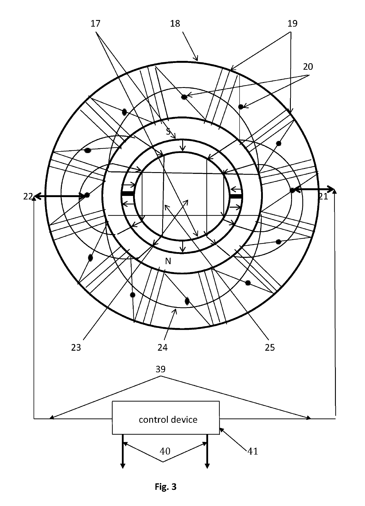
[0035]FIG. 3 shows an end view of the magnetic system of a DC power generator which consists of a rotor (17) with two beveled poles and a magnetically soft core of the stator (18) with tangential, connected in series to stator winding coils (19) and their electric terminals (contacts) (20) connected with the corresponding electric contacts (21) and (22) with terminals / wires (39) of a control device (41), which, in turn, at any point in time directs the induction electric current produced in the stator coils to the terminals of an external two-wire grid (40). At subsequent times, the control device selects new terminal / wires that connect the external two-wire grid with new contacts of the stator coil. The internal part of the rotor (23) is made of a nonmagnetic material. Lines (24) and (25) are magnetic lines of the stator (18) and the rotor (17), respectively.

[0036]Definition 5. The two-pole rotor shown in FIG. 3, which consists of a hollow cylinder with two equal-sized magnets loca...


PUM


Abstract

The invention belongs to the category of electric motors and power generators, and may expand the area of application, reduce costs, and increase the specific power and efficiency of electric machines. These electric machine comprise a rotor and a stator with winding coils and a control device. Stator winding coils are made as a system of radial and / or tangential coils connected in series and / or back-to-back; each coil has its own electric terminals. The control device connects its electric contacts with terminals of corresponding stator winding coils in order to provide a chain control of electric current supply to the corresponding stator coils and to create, at each point in time, a pre-determined stator magnetic field including a rotating or a reciprocating stator magnetic field, depending on the spatial position and the magnetic condition of the rotor. The invention can be applied to various fields of technology.

Description

FIELD OF TECHNOLOGY[0001]The invention described herein belongs to the electric motor and power generator category and may be used to generate electric and / or mechanical energy, to convert electric energy into mechanical energy and vice versa, etc. This electric machine is environmentally friendly and may be used in the power industry, the transport industry, mechanical engineering, the construction industry, astronautics, and other fields of technology.BACKGROUND ART[0002]Currently, the above tasks are performed partly by commutator and commutatorless machines (M. M. Katsman, Guide to electric machines [Moscow: Academy, 2005, ISBN 5-7695-1686-0], p. 9). Commutator machines include universal electric machines and direct current machines, for example, those with permanent magnets and excitation winding. Commutatorless machines include synchronous and asynchronous electric machines, for example, those with squirrel-cage and phase-wound rotor, single-phase, three-phase, capacitor-type,...

Claims


Application Information

Patent Timeline
Patent Type & Authority Patents(United States)
IPC IPC(8): H02K3/00H02K21/14H02K17/16H02P7/06H02K3/28H02K11/33H02K19/20
CPCH02K17/165H02K3/28H02K11/33H02K21/14H02P7/06H02K19/20H02K2201/03H02K17/26H02K7/06
Inventor LIMANSKIY, VALENTIN GRIGORYEVICH
Owner LIMANSKIY VALENTIN GRIGORYEVICH
Why Eureka
Try Eureka