
Manual test socket and method of adjustment

a test socket and manual technology, applied in the direction of electronic circuit testing, measurement devices, instruments, etc., can solve the problems of complex testing of microcircuits, failure to test, and ruining the entire board

Active Publication Date: 2019-12-03
JOHNSTECH INT
View PDF9 Cites 2 Cited by
  • Summary
  • Abstract
  • Description
  • Claims
  • Application Information

AI Technical Summary

Benefits of technology

The invention is related to a device that has a stop barrier to control the pressure on a device under test (DUT). The stop barrier is located to engage a longer pin in a through hole, which allows the longer pin to follow a path when the device is rotated. The stop barrier prevents the longer pin from moving further than a predetermined point, which defines the maximum pressure that can be applied to the DUT. This invention provides a reliable and consistent method to control the pressure on the DUT during testing.

Problems solved by technology

Soldering a defective microcircuit onto a circuit board often ruins the entire board, since typically it is either not possible or not economic to remove a defective microcircuit from a circuit board.
For a number of reasons, testing these microcircuits is complex.
In the first place, one should not solder the microcircuits to be tested into the test fixture because the act of removing the microcircuits when testing is complete might itself damage the microcircuit.
Failure to make proper contact with each microcircuit pin / contact may result in a failed test even if the microcircuit is not defective or a passed test for a bad chip.
It is not at all convenient to manually apply such a force for the entire duration of a longer test.
Two temporary situations arise where automated robotic force application to the microcircuit during testing is not convenient.
One of these situations is where a tester fails more than the expected percentage of microcircuits, where the tester is inconsistent in testing the same microcircuit or early in the production cycle where only a few chips need to be tested to build prototypes.
We find in these circumstances that using the tester loader element is inconvenient and applying force by hand to the package insufficiently precise and very difficult.
Prior art manual test sockets suffer from the difficulty of applying the right amount of force on the device under test (DUT) and then applying the same force consistently from DUT to DUT.

Method used


Image

  • Manual test socket and method of adjustment
  • Manual test socket and method of adjustment
  • Manual test socket and method of adjustment

Examples


Embodiment Construction

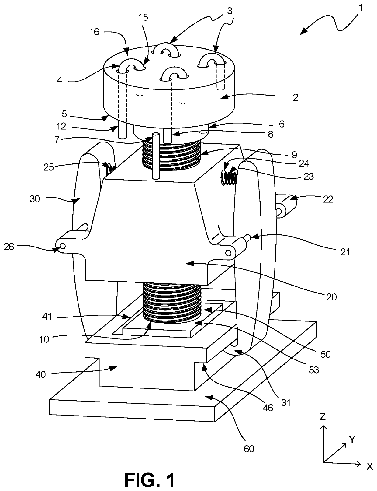
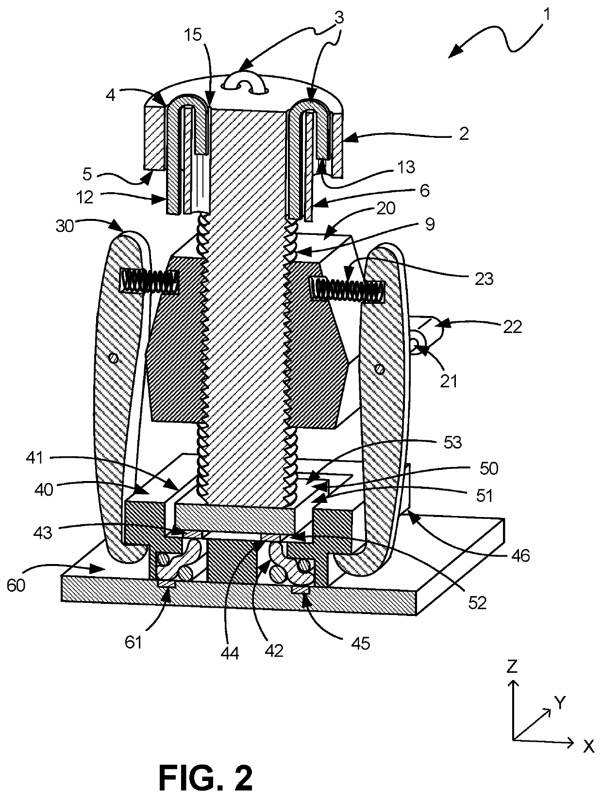
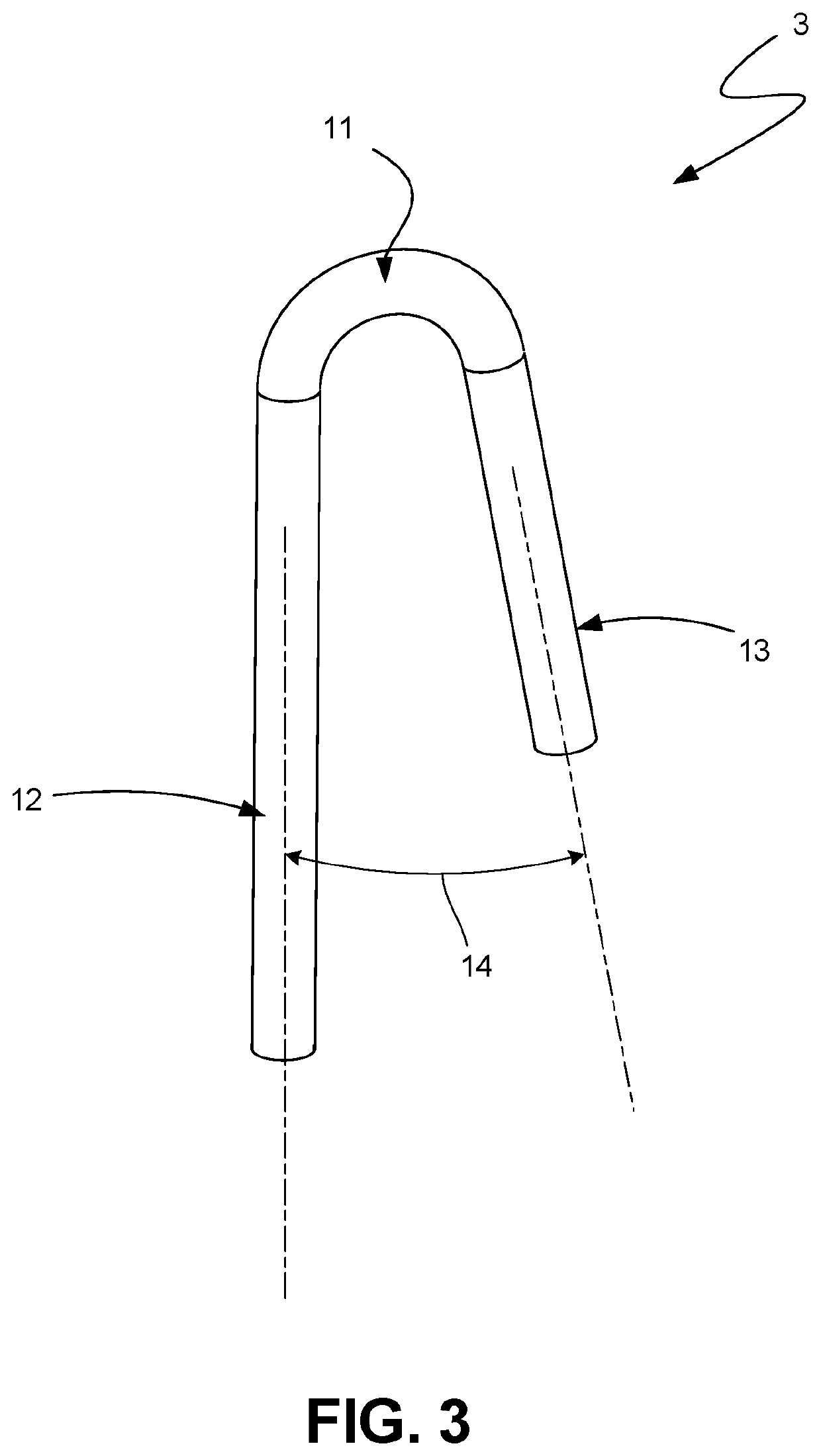
[0038]FIG. 1 and FIG. 2 are the preferred embodiments. FIG. 1 is an overall view of the assembly. FIG. 2 is the section view of the same assembly. FIG. 3 is an illustration of the “J-shaped” bent stop wire. FIG. 4 is an alternative embodiment.

[0039]To perform these connections reliably with consistent contact resistance from the IC device (DUT) pad 52 to the circuit board trace / pad 61 on the load board 60, the IC device / DUT 50 must be presented onto conductive elements 42 (contact pins of types known in the art, such as shown in U.S. Pat. Nos. 8,536,889 and 8,558,554, incorporated herein by reference) in a very accurate position both above the test socket housing 40 (Z-axis) and in the lateral directions (X-axis and Y-axis). This lateral direction control is usually achieved by limiting the device sidewalls 51 X and Y-play to within an alignment window frame 41 at the top opening of the housing. As an example, for a square shaped profile device 50 a square shaped window 41 on top of...


PUM


Abstract

A test device for manually testing chips / ICs is disclosed. A housing includes a receiver for a device under test (DUT). The DUT must be pressed into the housing to make adequate contact with the test pins in the bottom of the test device. A screw drive presses the DUT into position and a plurality of holes in the turning knob accommodate through-going pins which on one leg extend through the knob and into an interference path of a fixed barrier stop. The extended leg then engages the stop during rotation to end the downward movement of the screw. Adjustment is made by selecting holes where the pins are inserted. Reversing the pins in the hole allows for storage of the pins when not in use.

Description

TECHNICAL FIELD[0001]This disclosure relates to the field of microcircuit / IC testing devices, more particularly, a manual test socket / actuator used to manually test single chips.BACKGROUND[0002]Microcircuits are well known electrical components that combine hundreds or thousands of individual circuit components and connections in a small volume. The package that holds a typical microcircuit may be no larger than 5 mm. square by 0.5 mm thick. One common type of container for a microcircuit called a leadless package, has small connector or contact pads along the periphery of one surface of the package. A single package may have several dozen contact pads by which power is supplied to the microcircuits and signals sent to and from the microcircuit. The contact pads are soldered onto the conductors of a circuit board during assembly of the electrical device.[0003]Before a microcircuit is soldered onto a circuit board, the microcircuit must be tested to assure design functionality. Solde...

Claims


Application Information

Patent Timeline
IPC IPC(8): G01R31/28
CPCG01R31/2891
Inventor LOPEZ, JOSEATTARAN, MEHDI
Owner JOHNSTECH INT
Learn More