Homogenizer comprising a light source

a technology of light source and homogenizer, which is applied in the field of homogenizer, can solve the problems of optical loss, additional expenses of light elements,

Active Publication Date: 2019-12-10
IVOCLAR VIVADENT AG
View PDF21 Cites 0 Cited by
  • Summary
  • Abstract
  • Description
  • Claims
  • Application Information

AI Technical Summary

Benefits of technology

[0033]It is thus especially beneficial for the LED chips to be arranged within the hollow element operating as a reflector. The emitted radiation is completely reflected, and is reflected in inclined angles and several times, which is beneficial to homogenization.

Problems solved by technology

Said hollow elements suffer from the additional expenses and optical losses, which are generated by such a homogeniser as an ancillary part, so that such homogenisers, as a general rule, will not be employed.

Method used


Image

  • Homogenizer comprising a light source
  • Homogenizer comprising a light source
  • Homogenizer comprising a light source

Examples


Embodiment Construction

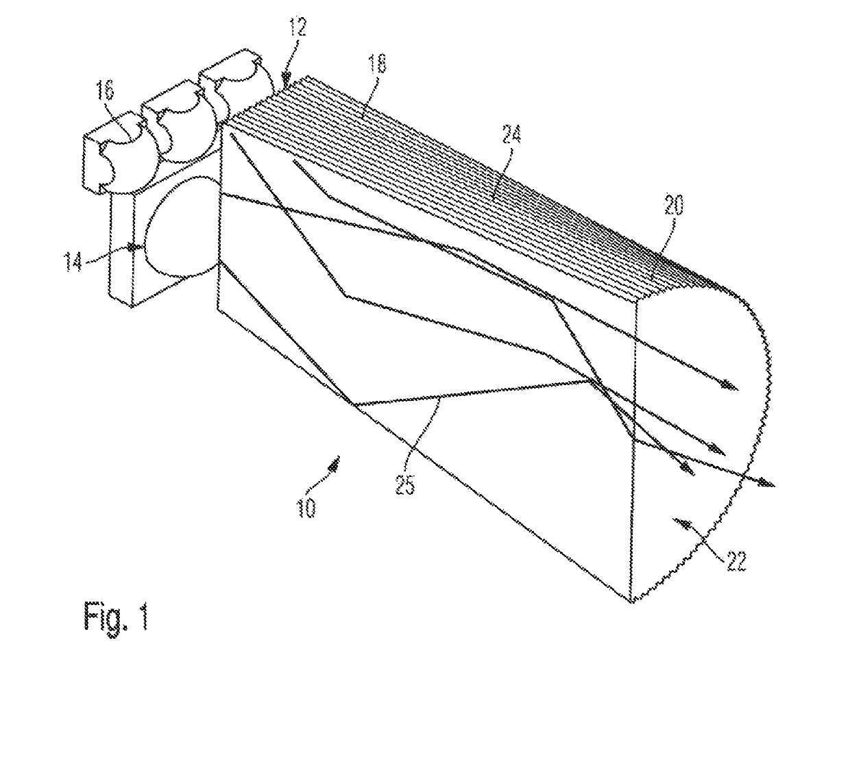
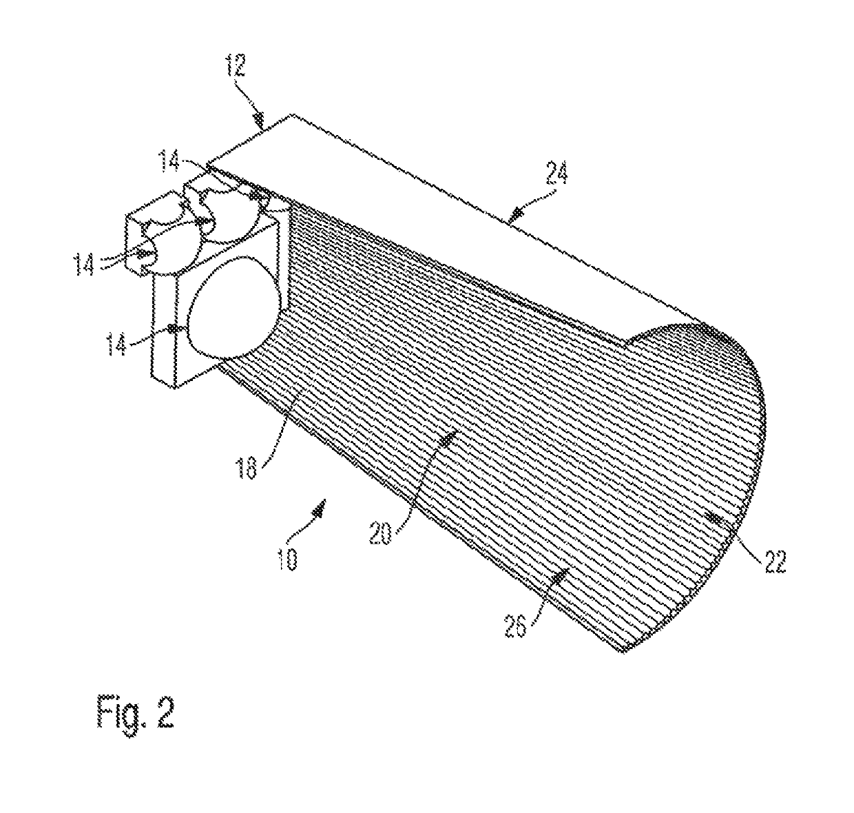
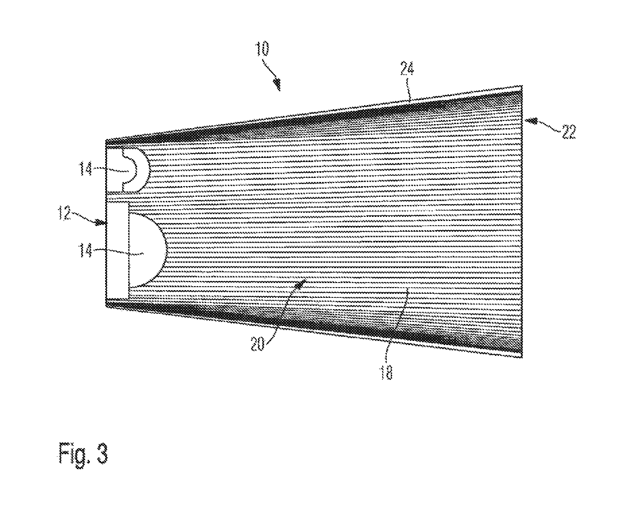
[0052]From FIG. 1, an exemplary homogeniser 10 as part of a light curing apparatus may be seen. Adjacent to an input surface 12 of the homogeniser 10, a plurality of LED chips 14 are arranged, which each are individually cast with a transparent casting compound 16 to form collecting lenses. In this working example, the cast LED chips 14 are spaced apart from the input surface. The input surface 12 is about squared, wherein in FIG. 1 a rectangular shape is represented, after the homogeniser 10 is represented as being cut-away.

[0053]The homogeniser 10 is formed as a hollow element, comprising a corrugation 18 at its outer circumference. The corrugation 18 consists of a multitude of ribs 20, which are evenly distributed across the circumference. The ribs 20 extend, in the course of the homogeniser, along the outer circumference, i.e. from the input surface 12 to an output surface 22.

[0054]In the working example represented, the ribs 20 are formed as triangular ribs. The material formin...


PUM


Abstract

The invention relates to a homogenizer having an input surface and an output surface which are incongruent to one another, at least one inclined surface extending between the input surface and the output surface. The inclined surface is corrugated. According to the invention, the homogenizer is designed as a hollow element which surrounds the LED chips (14) reflectively.

Description

CROSS-REFERENCE TO RELATED APPLICATIONS[0001]This application is a National Stage application of International patent application PCT / EP2016 / 081163 filed on Dec. 16, 2016, which claims priority to European patent application No. 15200486.7 filed on Dec. 16, 2015, the disclosures of which are incorporated herein by reference in their entirety.FIELD OF THE INVENTION[0002]The invention relates to a homogeniser, and more particularly to a light curing apparatus having a homogeniser.BACKGROUND OF THE INVENTION[0003]In light curing apparatuses, especially for dental purposes, it has been known for long to use an optical fiber, to guide the light originating from the light source to the treatment site. The optical fiber may be formed as a light guide rod or as a light fiber rod, or also as a combination thereof.[0004]Typically, as light sources, LED chips but also laser chips are used, which each emit a predetermined wavelength spectrum, and exciting the intermixed photo initiator, for exa...

Claims


Application Information

Patent Timeline
Patent Type & Authority Patents(United States)
IPC IPC(8): G02B19/00A61B1/06G02B27/09A61C13/15F21V8/00F21Y115/10
CPCA61C19/003G02B27/0994G02B6/0008G02B27/0977A61B1/06G02B19/0028G02B6/0096F21Y2115/10G02B19/0019G02B19/0061
Inventor SENN, BRUNOPAULER, MARKUS
Owner IVOCLAR VIVADENT AG
Why Eureka
Try Eureka