Eureka AIR delivers breakthrough ideas for toughest innovation challenges, trusted by R&D personnel around the world.

Vibrating device comprising embedded mechanical reflectors for defining an active plate mode propagation area and mobile apparatus comprising the device

Active Publication Date: 2019-12-10
COMMISSARIAT A LENERGIE ATOMIQUE ET AUX ENERGIES ALTERNATIVES +2
View PDF15 Cites 0 Cited by
  • Summary
  • Abstract
  • Description
  • Claims
  • Application Information

AI Technical Summary

Benefits of technology

The present invention proposes a solution to prevent distortion of plate modes in a support with a defect (such as edge defect or structural heterogeneity). One solution is to use an embedded mechanical reflector with discrete elements separated from each other by a distance to isolate the defect from the active zone. This results in improved performance and stability of the support.

Problems solved by technology

Generally, the vibration modes are well controlled in the context of a rectangular plate and are disrupted when the geometry used is unconventional and has, for example, rounded corners.
However, none of these references proposes any solution making it possible to retain, in these plates with rounded corners, a mode such as that which can be obtained in a rectangular plate, for example by modifying the limit conditions.
These references do not present any solutions making it possible to overcome the defect present to obtain a wave of desired form.

Method used


Image

  • Vibrating device comprising embedded mechanical reflectors for defining an active plate mode propagation area and mobile apparatus comprising the device
  • Vibrating device comprising embedded mechanical reflectors for defining an active plate mode propagation area and mobile apparatus comprising the device
  • Vibrating device comprising embedded mechanical reflectors for defining an active plate mode propagation area and mobile apparatus comprising the device

Examples


first exemplary embodiment

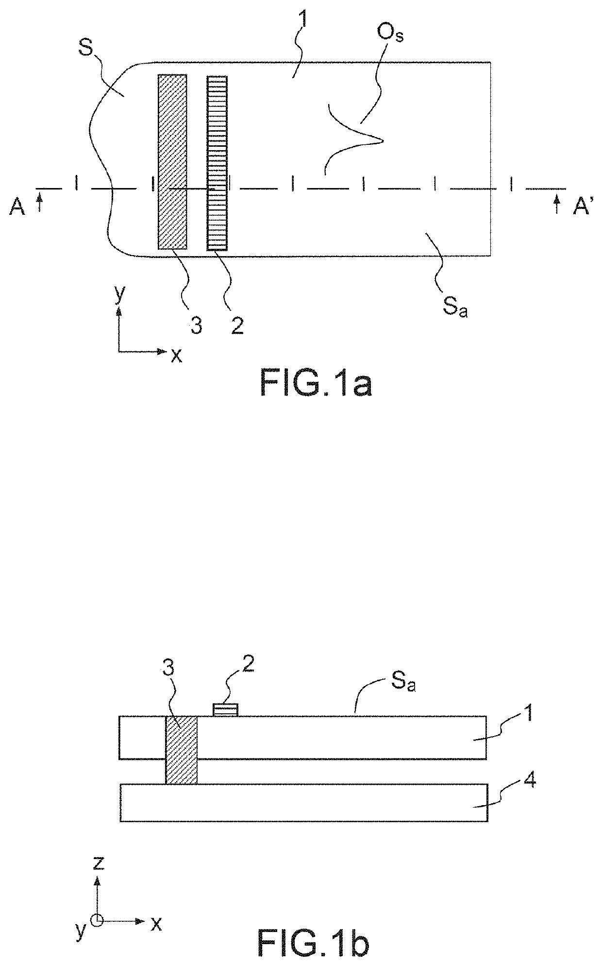
[0116]The embodiments can depend on the application targeted. In many cases, like that of haptics, producing an embedded mechanical reflector ensuring at least an immobilization in the direction Z is “easy” to implement through fixing a plate ensuring the first support in synergy with a casing secured to said first support.

[0117]The embedded mechanical reflector must prevent the movement of the plate in the direction Z. It can for example be ensured by gluing the casing with the resonant plate. The glued region at the level of said plate constituting the embedded mechanical reflector.

[0118]The bead of glue has dimensions on x, y (in the plane) dimensioned like those described previously so as to produce an embedded mechanical reflector with the desired dimensions.

[0119]The thickness of glue can also be set according to the material used. The glue can be an epoxy glue, a UV glue or any other suitable glue. This configuration is illustrated in FIG. 16 and highlights:[0120]a first supp...

second exemplary embodiment

[0124]According to this second example, the embedded mechanical reflector consists of a snap-fitting of the face plate onto the casing. In this case, the vibrating face plate is machined by laser, ion machining or any other suitable method so as to partially etch the face plate in the embedment zones provided by the dimensioning step and thus define the cavities.

[0125]This etching can have a depth ranging from a few micrometers to several hundreds of micrometers. Opposite, the casing has pins, produced at the same time in the same material as that of the casing, or produced subsequently and possibly in a material other than that of the casing. The dimensions on the axes X and Y of the pins are set by the dimensions of the opposite cavities (and by design rules for the insertion of the pins to induce the fixing thereof at the face plate level). The height of the pins is matched to the depth of the cover. Upon assembly of the casing and of the vibrating face plate, the pins are insert...


PUM


Abstract

A vibrating device comprises: a first support configured to be deformed having a surface defined in a plane in directions X and Y; at least one actuator configured to generate plate modes propagated in the first support; the first support comprising: at least one defect with respect to the propagation of the plate modes; the defect being of geometrical nature or corresponding to a structural heterogeneity; comprising: a second support; at least one embedded mechanical reflector secured to the first support and in contact with the first support, configured to immobilize the first support in at least one direction Z at right angles to the directions X and Y, the mechanical reflector being secured to the second support and; the embedded mechanical reflector being configured to isolate a so-called active zone belonging to the surface defined in a plane in directions X and Y in which the plate modes are propagated, the active zone excluding the defect; the actuator being situated in the active region.

Description

CROSS-REFERENCE TO RELATED APPLICATIONS[0001]This application is a National Stage of International patent application PCT / EP2015 / 078478, filed on Dec. 3, 2015, which claims priority to foreign French patent application No. FR 1462035, filed on Dec. 8, 2014, the disclosures of which are incorporated by reference in their entirety.FIELD OF THE INVENTION[0002]The field of the invention is that of the vibrating supports that can be used in many applications and notably that relating to the haptic interface corresponding to a technology in which an object can interact with the environment by the sense of touch and which is particularly advantageous for cell phones.BACKGROUND[0003]In effect, currently, the manufacturers of cell phones who have ventured into the touchscreen mobile sector are seeking to be distinguished by incorporating a haptic interface. Thus, when a user slides his or her finger over an icon situated on the screen, he or she can feel a slight vibration originating from t...

Claims


Application Information

Patent Timeline
IPC IPC(8): G06F3/01G10K11/20G10K11/36G06F1/16B06B1/06
CPCG06F1/1626G06F3/016G06F1/1688G10K11/20G10K11/36B06B1/0648B06B1/0644G06F1/1684
Inventor CHAPPAZ, CÉDRICKCASSET, FABRICEBASROUR, SKANDARGORISSE, MARIE
Owner COMMISSARIAT A LENERGIE ATOMIQUE ET AUX ENERGIES ALTERNATIVES
Why Eureka
Eureka Blog
Learn More