Reflectometry instrument and method for measuring macular pigment

a reflection measurement and instrument technology, applied in the field of reflection measurement instruments, can solve the problems of affecting the vision of people with macular degeneration, affecting the ability to read, recognize faces, drive safely on unfamiliar surfaces, and only providing coarse resolution to surrounding parts of the macula

Active Publication Date: 2019-12-17
ZEAVISION LLC
View PDF25 Cites 2 Cited by
  • Summary
  • Abstract
  • Description
  • Claims
  • Application Information

AI Technical Summary

Benefits of technology

[0017]According to still further aspects, a reflectometry instrument is provided to measure macular pigment of a macula of a human eye. The instrument includes a housing having an illumination system, a detection system, and a beam dump. The illumination system is configured to generate an illumination beam and direct the illumination beam to the macula. A detection beam is generated as a portion of the illumination beam reflected by the macula. The detection system is configured to receive and measure the detection beam to determine an amount of the macular pigment in the macula. The beam dump is in optical alignment with an optical input of the detection system for absorbing stray light within the reflectometry instrument. The instrument also includes an eyepiece connected to the housing, which is configured to interface with the human eye to prevent ambient light from entering the housing. The beam dump and the eyepiece allow the reflectometry instrument to measure the macular pigment of the macula in a lit environment.

Problems solved by technology

People who suffer from macular degeneration often lose the ability to read, recognize faces, drive, or walk safely on unfamiliar routes.
The surrounding portions of the macula can only provide coarse resolution.
This process occurs so rapidly that a person does not notice it happening, and does not pay attention to how a complete visual image and impression is being assembled and updated from combinations of fine and coarse resolution images.
It includes any progressive disorder or disease that causes the macula to gradually degenerate, to a point that substantially impairs or damages eyesight and vision.
For example, many instruments require the eye to be dilated before use, which can be uncomfortable to the patient and add extra time and cost to the procedure.

Method used


Image

  • Reflectometry instrument and method for measuring macular pigment
  • Reflectometry instrument and method for measuring macular pigment
  • Reflectometry instrument and method for measuring macular pigment

Examples


Embodiment Construction

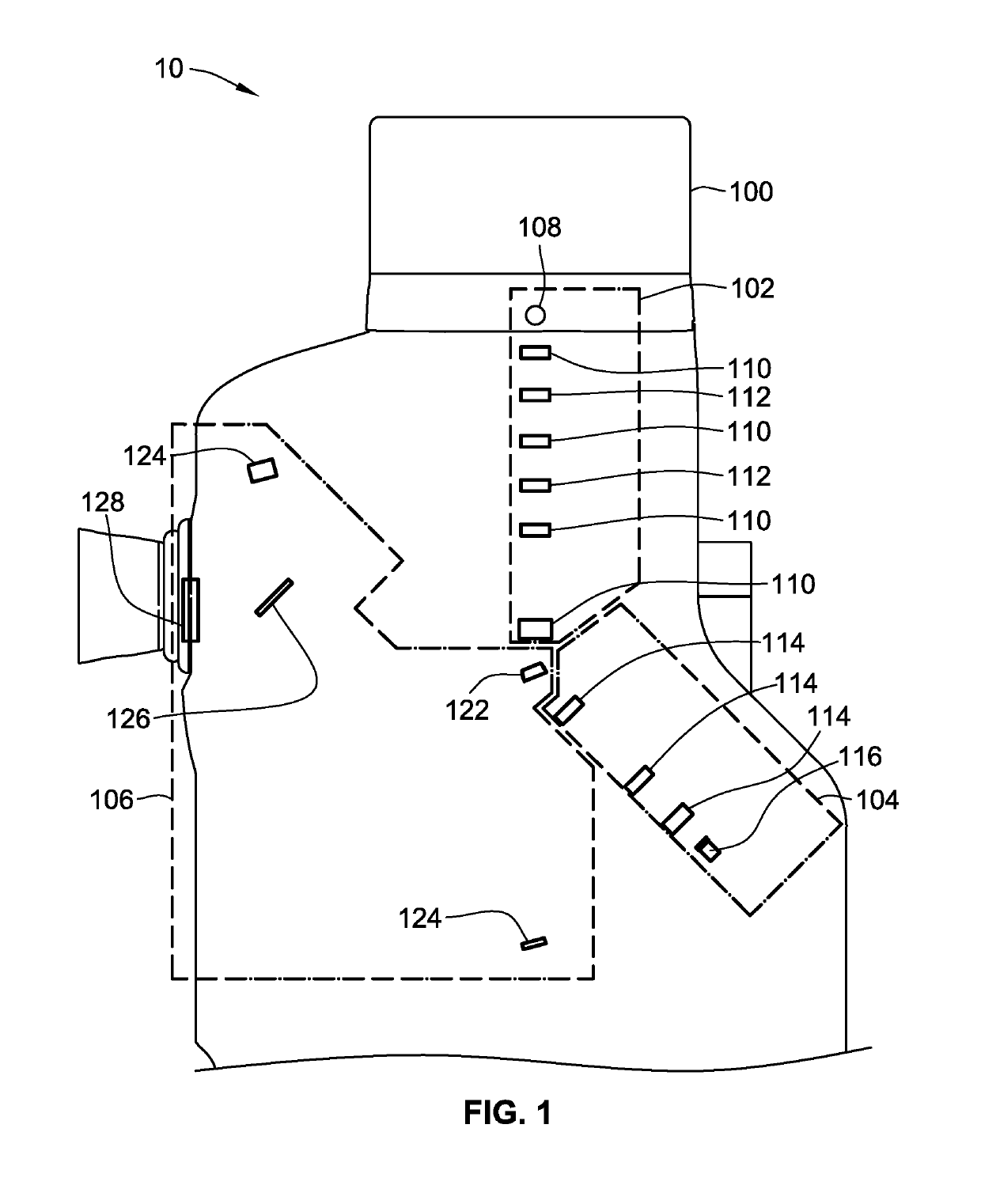
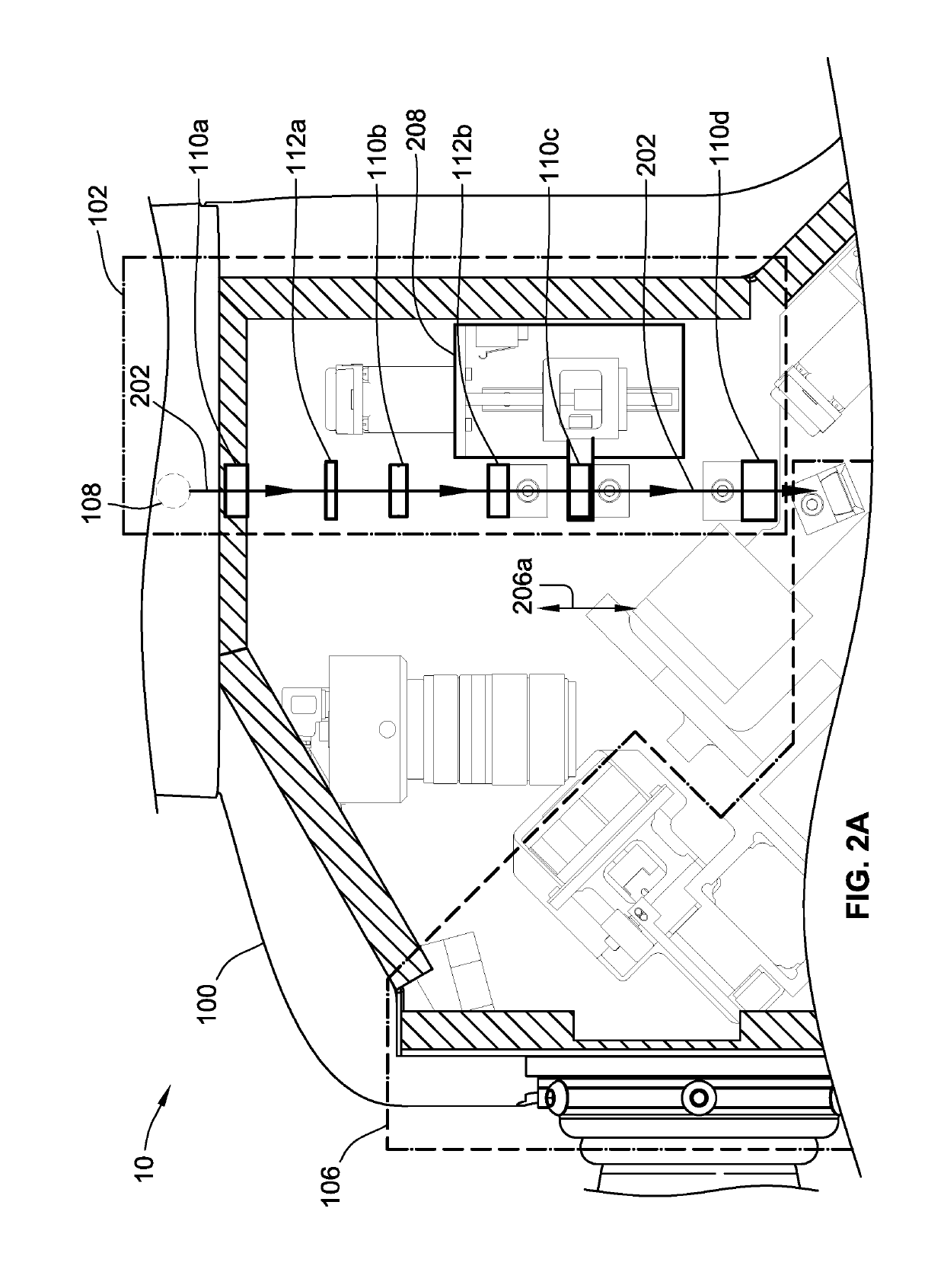
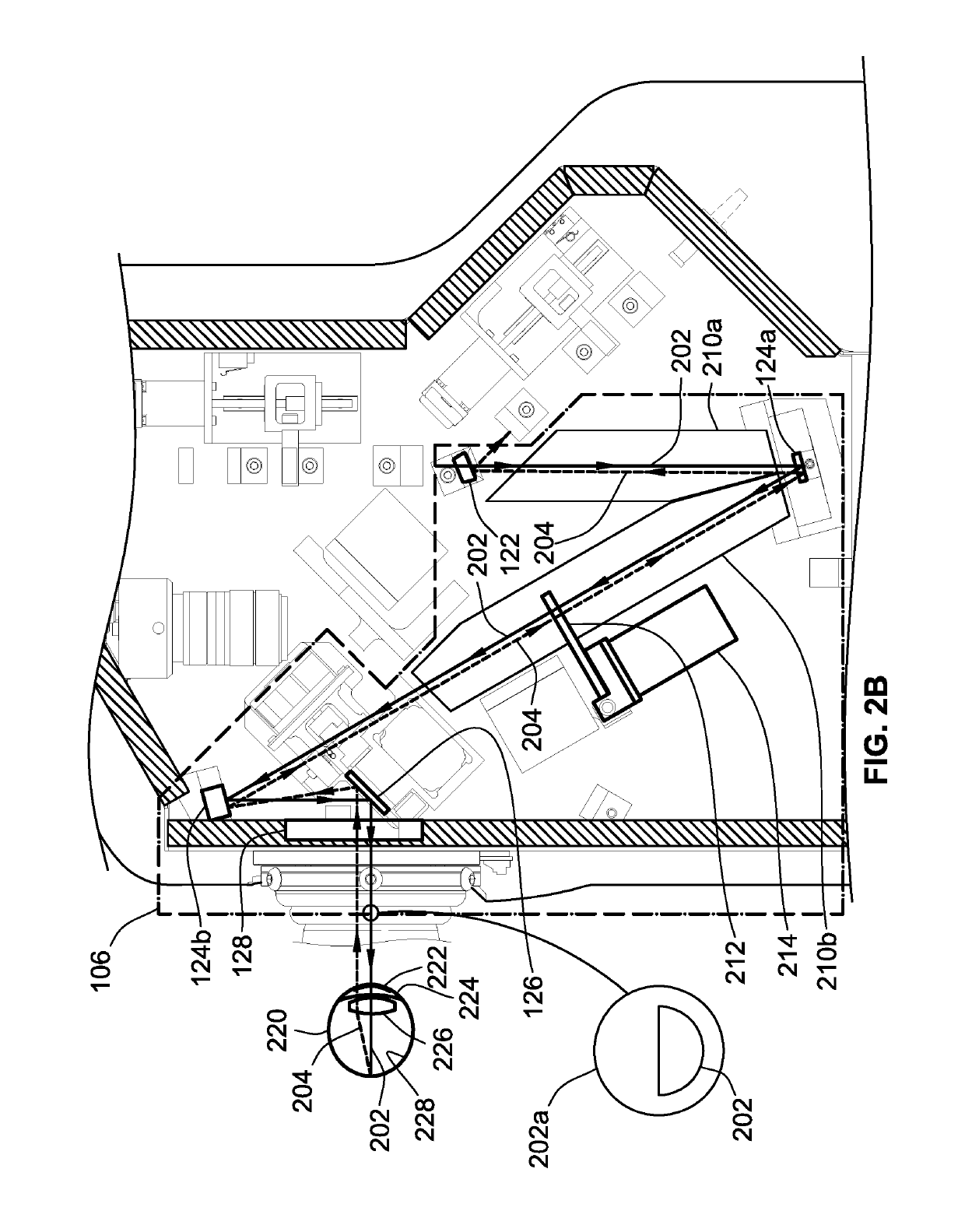
[0028]FIG. 1 illustrates a reflectometry instrument 10 adapted to measure characteristics of a human eye. The reflectometry instrument 10 will be described in reference to three main systems: an illumination system 102, a detection system 104, and a separation system 106, all of which are contained within an upper housing 100 of the reflectometry instrument 10. The illumination system 102 includes a light source 108, a plurality of lenses 110, and a plurality of masks 112. The illumination system 102 generates an illumination beam having certain characteristics that will be transmitted to the patient's eye. As mentioned above, the reflectometry instrument 10 may be used on an un-dilated pupil, making the instrument 10 much easier to use and decreasing the time required to test a patient's eye.

[0029]The detection system 104 includes a plurality of lenses 114 and a fiber optic cable 116. The detection system 104 receives a detection beam, which is a portion of the illumination beam th...


PUM


Abstract

A reflectometry instrument includes a light source for emitting an illumination beam that illuminates the macula. A portion of the illumination beam is reflected from the macula and forms a detection beam. The detection beam is indicative of macular pigment in the macula. The instrument also includes a first mirror for reflecting the illumination beam toward the macula and for reflecting the detection beam from the macula. The instrument is configured so that the illumination beam and the detection beam remain separated between the macula and the first mirror.

Description

CROSS-REFERENCE TO RELATED APPLICATION(S)[0001]The present application claims the benefit of and priority to U.S. Provisional Patent Application No. 62 / 464,028, filed Feb. 27, 2017, entitled “REFLECTOMETRY INSTRUMENT AND METHOD FOR MEASURING MACULAR PIGMENT,” which is hereby incorporated by reference herein in its entirety.FIELD OF THE INVENTION[0002]The present invention relates to a reflectometry instrument that measures characteristics of the patient's eye, such as macular pigment, with a high degree of accuracy and without dilating the patient's pupil.BACKGROUND OF THE INVENTION[0003]The retina is the layer of nerve cells at the back of the eye, which convert light into nerve signals that are sent to the brain. In humans, and in other primates (but not in most other mammals, or other types of animals), the retina has a small yellowish area in the center of the field of vision. That yellowish area is called the “macula.” It provides fine-resolution vision in the center of the vis...

Claims


Application Information

Patent Timeline
Patent Type & Authority Patents(United States)
IPC IPC(8): A61B3/12G01J3/42A61B3/10G01J3/02A61B3/15A61B3/00A61B3/14
CPCG01J3/0237G01J3/021A61B3/145A61B3/152G01J3/0208G01J3/42A61B3/12A61B3/0025G01J3/0202G01J3/0229A61B3/10G01J3/0218A61B3/0008A61B3/0083
Inventor HUTER, SCOTT J.MAGRINI, KEVIN MARTINDEHOOG, EDWARD ALLENBURKE, JEFF ALANENGEL, NATHAN FRANKLIN
Owner ZEAVISION LLC
Why Eureka
Try Eureka