Method and device for the testing of ultrasound probes

a technology for ultrasound probes and probes, applied in the direction of instruments, ultrasonic/sonic/infrasonic image/data processing, mechanical vibration separation, etc., can solve the problem of slow relays and achieve the effect of fast switching capabilities

Active Publication Date: 2019-12-17
BBS FORSALJNINGS
View PDF11 Cites 1 Cited by
  • Summary
  • Abstract
  • Description
  • Claims
  • Application Information

AI Technical Summary

Benefits of technology

[0011]The device has several advantages. It has the advantage that it has faster switching capabilities. This makes it possible to detect crosstalk in a manner described above. Since the probe-specific information to a great extent is encoded in software and not hardware it is easier to change and to adapt, and to distribute. Furthermore, the fast switching makes enables the device to produce a real time image. This can be used to improve the diagnosis of the probe.
[0014]The device may provide an image is an image that is able to show relative motion (Doppler mode imaging). This has the advantage that more specific information about the probe may be provided.
[0016]This has the advantage that probes from several different manufactures can be tested with the device.
[0017]The interrogation protocol may comprise information about which type of adapter that should be connected to the device. This makes it easier for the user to select the appropriate adapter.
[0021]The method according may include the step of displaying information to a user about which adapter that is to be connected to the device, where said information is stored in the interrogation protocol. This makes it easier for the user to select the appropriate adapter.

Problems solved by technology

Problems with the probe may include problems with the leads, crosstalk between leads and errors in the transducers such as air under the lens, detachment of the backing material of the piezoelectric crystal, detachment of the piezoelectric crystal, and the transducers changing frequency.
However, relays are slow and it would be desirable to have a probe testing device with faster switching capabilities.

Method used


Image

  • Method and device for the testing of ultrasound probes
  • Method and device for the testing of ultrasound probes
  • Method and device for the testing of ultrasound probes

Examples


Embodiment Construction

[0029]“Ultrasound probe” refers to an acoustic device having a plurality of transducing elements adapted for conversion between electric and acoustic signals and between acoustic signals and electric signals, and leads for connecting each of the transducer elements to an ultrasound machine for example an ultrasound imaging machine. Typically the transducing elements are piezoelectric crystals. The transducer element and its lead may be referred to as “transducer element / lead pair” herein.

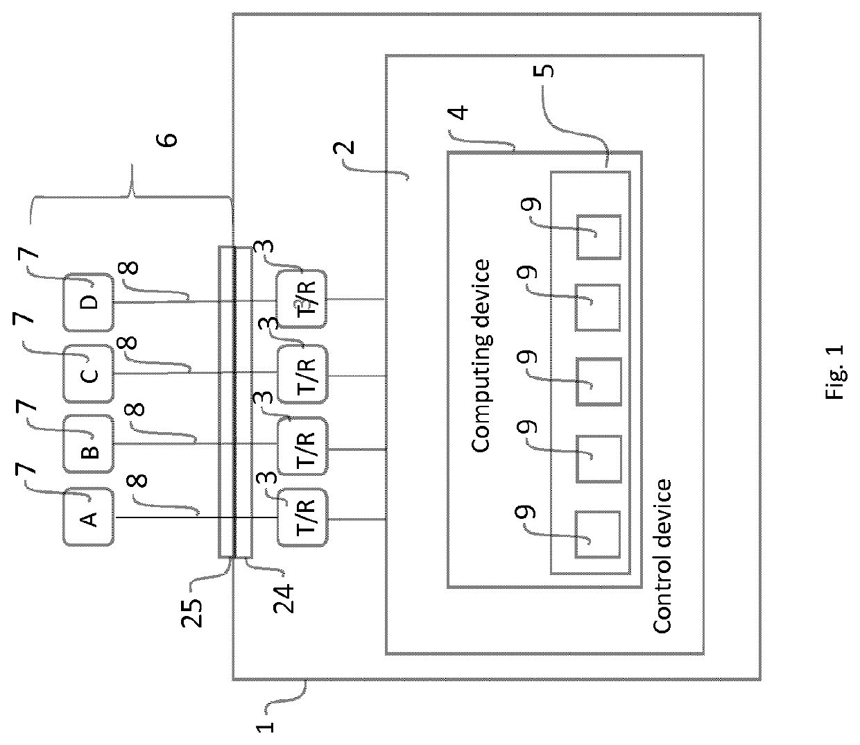
[0030]With reference to FIG. 1, the device 1 comprises a control device 2, which controls a plurality of transmitter / receiver circuits 3 (four transmitter / receiver circuits are shown in FIG. 1). The control device comprises at least one computing device 4, which preferably can store software in a memory 5. The computing device can be any suitable computer capable of executing software, for example a mainframe, a PC or a laptop.

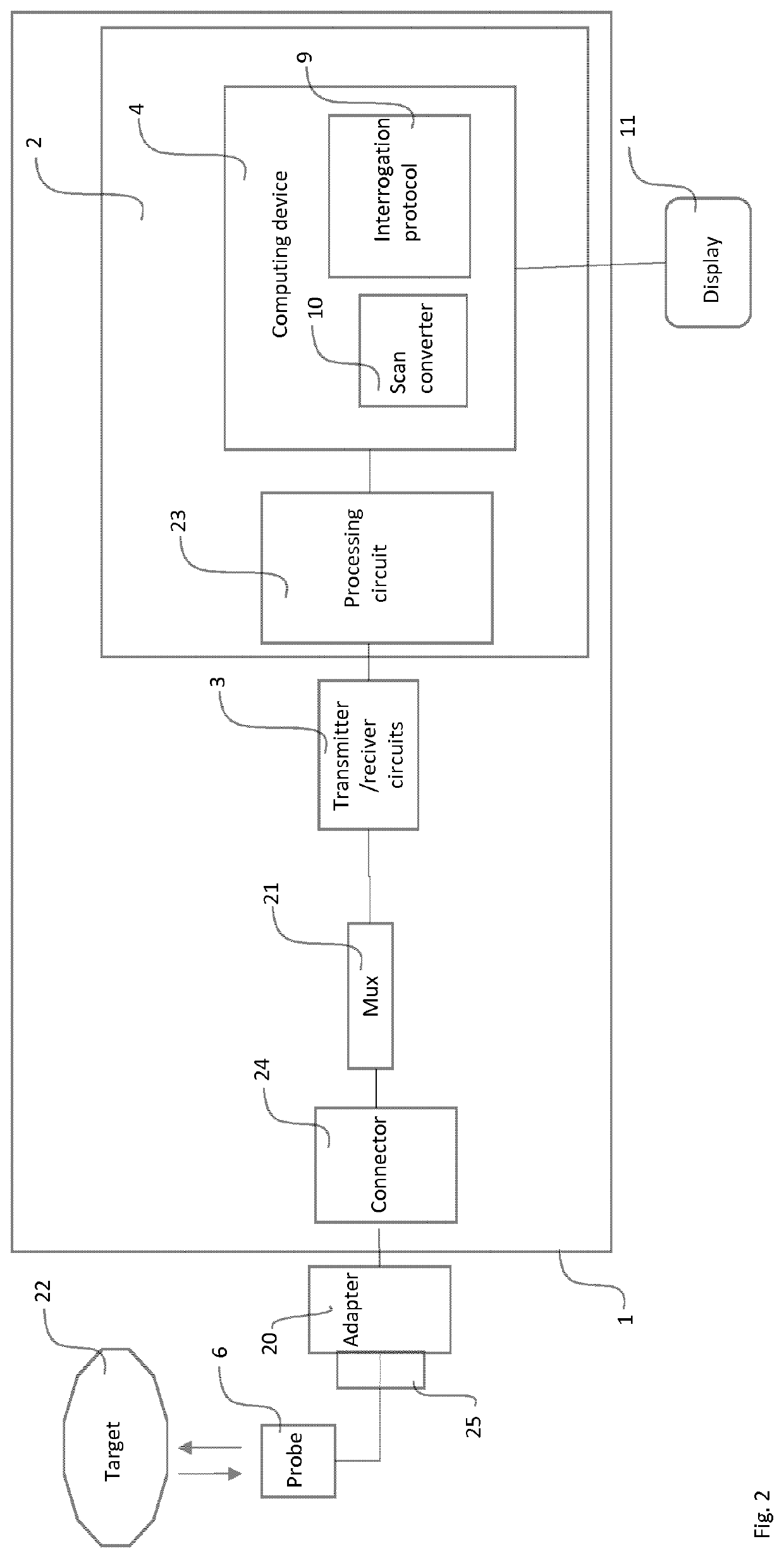
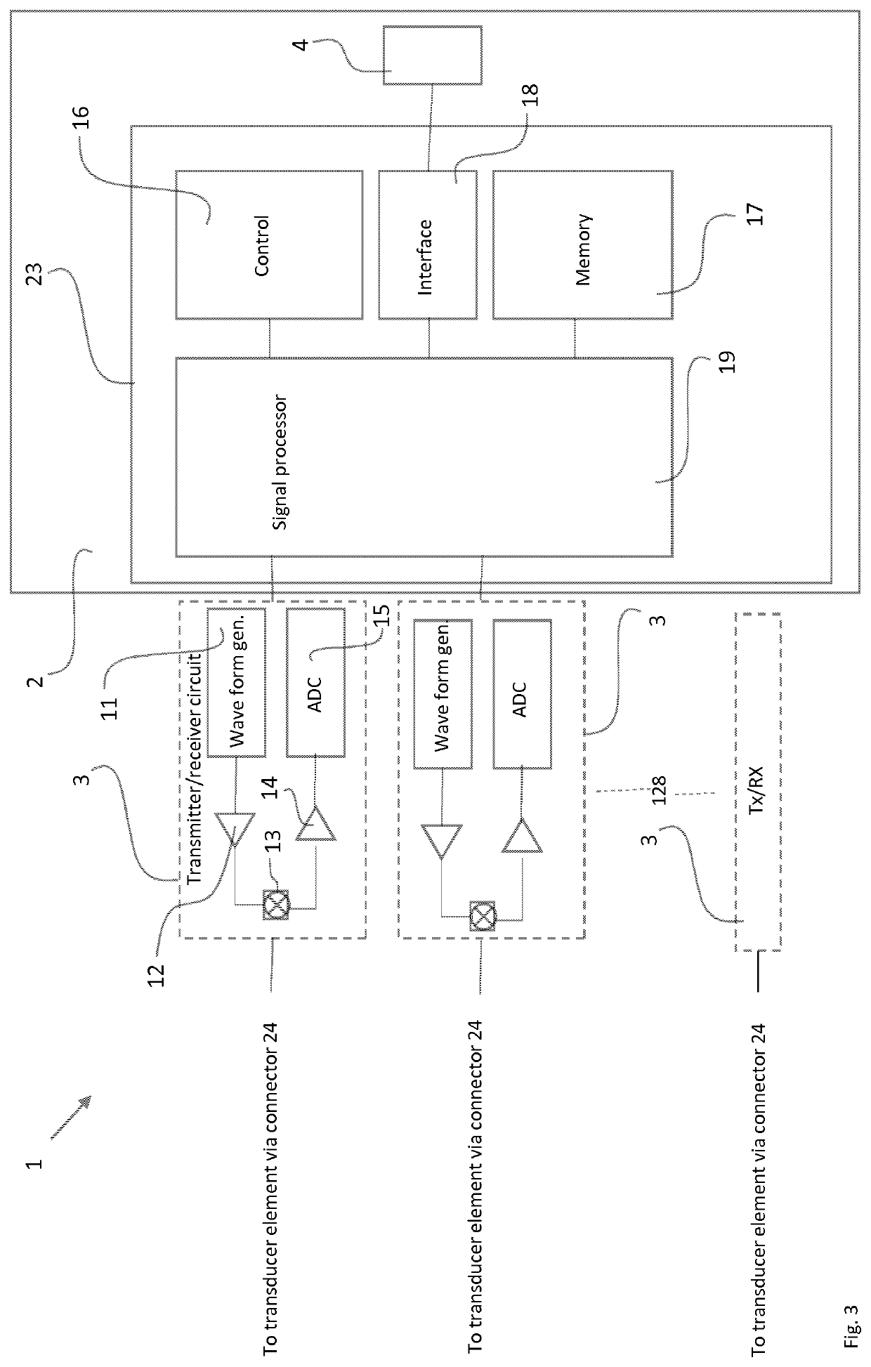
[0031]An example of the arrangement of the transmitter / receiver circuits ...


PUM

PropertyMeasurementUnit
frequencyaaaaaaaaaa
voltageaaaaaaaaaa
voltageaaaaaaaaaa

Abstract

There is provided a device for testing ultrasound probes comprising a plurality of transducing elements, said device comprising a plurality of ultrasound transmitter / receiver circuits, a computing device and a control device arranged to control the transmitter / receiver circuits and the computing device arranged to select an interrogation protocol from a plurality of different interrogation protocols, where each interrogation protocol comprises instructions for the order in which the plurality of transmitter / receiver circuits shall send voltage pulses to the transducers of the ultrasound probe.

Description

FIELD OF THE INVENTION[0001]This invention relates to a device for testing ultrasound probes.BACKGROUND[0002]Ultrasound is frequently used in healthcare, for example in diagnosis and for monitoring pregnancies. Ultrasound is also used for detection of structural defects for example in machinery; and for other purposes. Ultrasound technology relies on detecting the scattering of sound waves. Sending and receiving the ultrasound wave is usually carried out with a piezoelectric transducer that can generate a sound wave upon receiving a voltage pulse and generate a voltage pulse upon receiving a sound wave.[0003]Ultrasound probes consist of a plurality of piezoelectric crystals that each are controlled by a lead capable of sending and receiving voltage pulses. Ultrasound images are generated by transforming the voltage pulses that are generated by the transducers when they receive sound echoes caused by the previously sent ultrasound waves.[0004]An ultrasound probe comprises several tra...

Claims


Application Information

Patent Timeline
Patent Type & Authority Patents(United States)
IPC IPC(8): G01N29/30G01N29/26A61B8/08A61B8/00B06B1/02
CPCA61B8/488B06B1/0215G01N29/30A61B8/58A61B8/4494A61B8/461A61B8/56G01N29/262A61B8/587A61B8/54A61B8/4444G01N2291/106B06B2201/40G01S7/5205
Inventor SEGALL, BJÖRN
Owner BBS FORSALJNINGS
Why Eureka
Try Eureka