Antenna assembly for a vehicle

a technology for vehicles and antennas, applied in circuit electrical arrangements, independent non-interaction antenna combinations, cross-talk/noise/interference reduction, etc., can solve problems such as signal losses

Active Publication Date: 2019-12-17
AIRGAIN INC
View PDF100 Cites 10 Cited by
  • Summary
  • Abstract
  • Description
  • Claims
  • Application Information

AI Technical Summary

Problems solved by technology

The long coaxial cable that connects a modem to an antenna on a vehicle leads to signal losses due to the length of the coaxial cable.

Method used


Image

  • Antenna assembly for a vehicle
  • Antenna assembly for a vehicle
  • Antenna assembly for a vehicle

Examples


Embodiment Construction

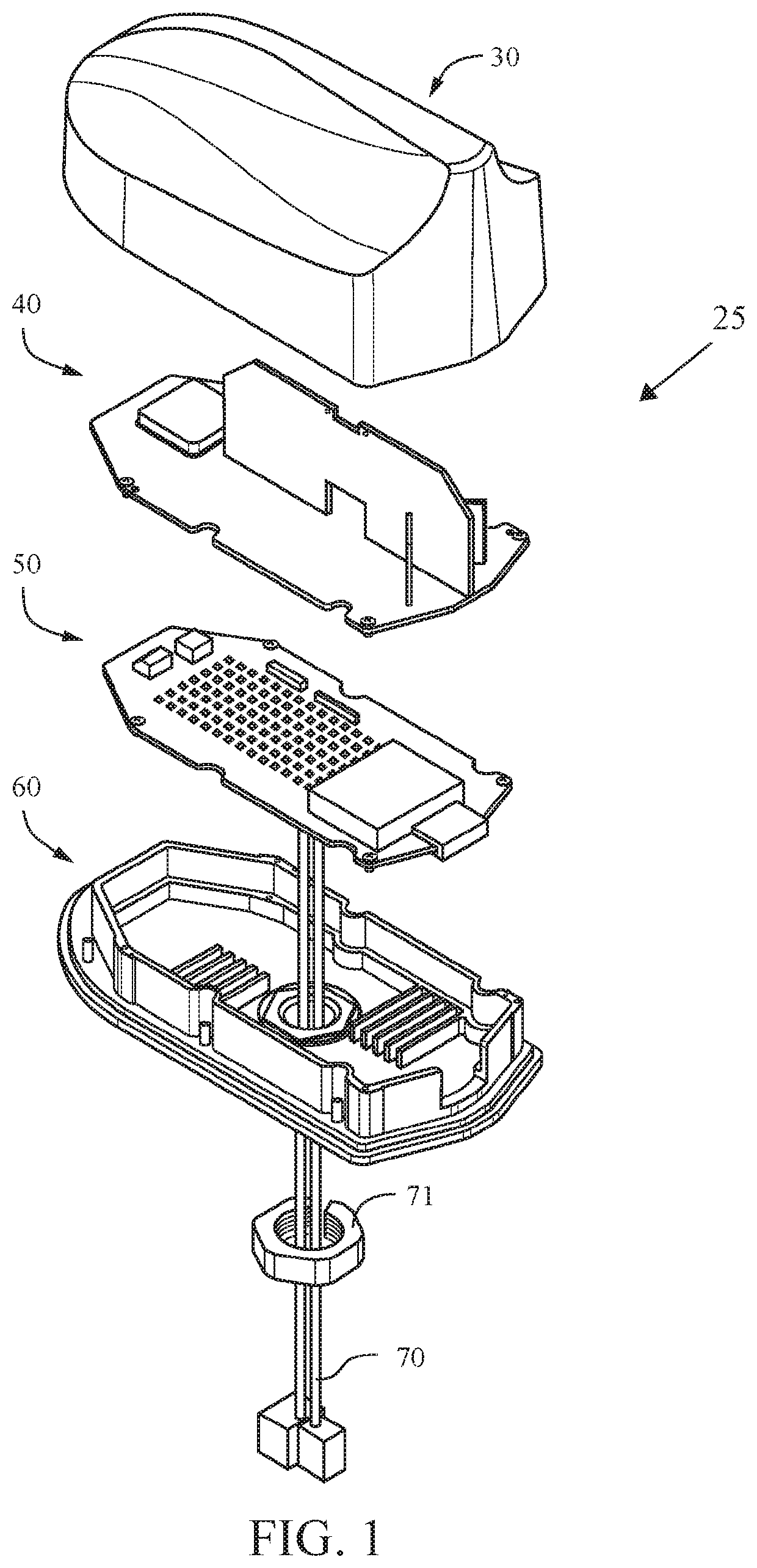
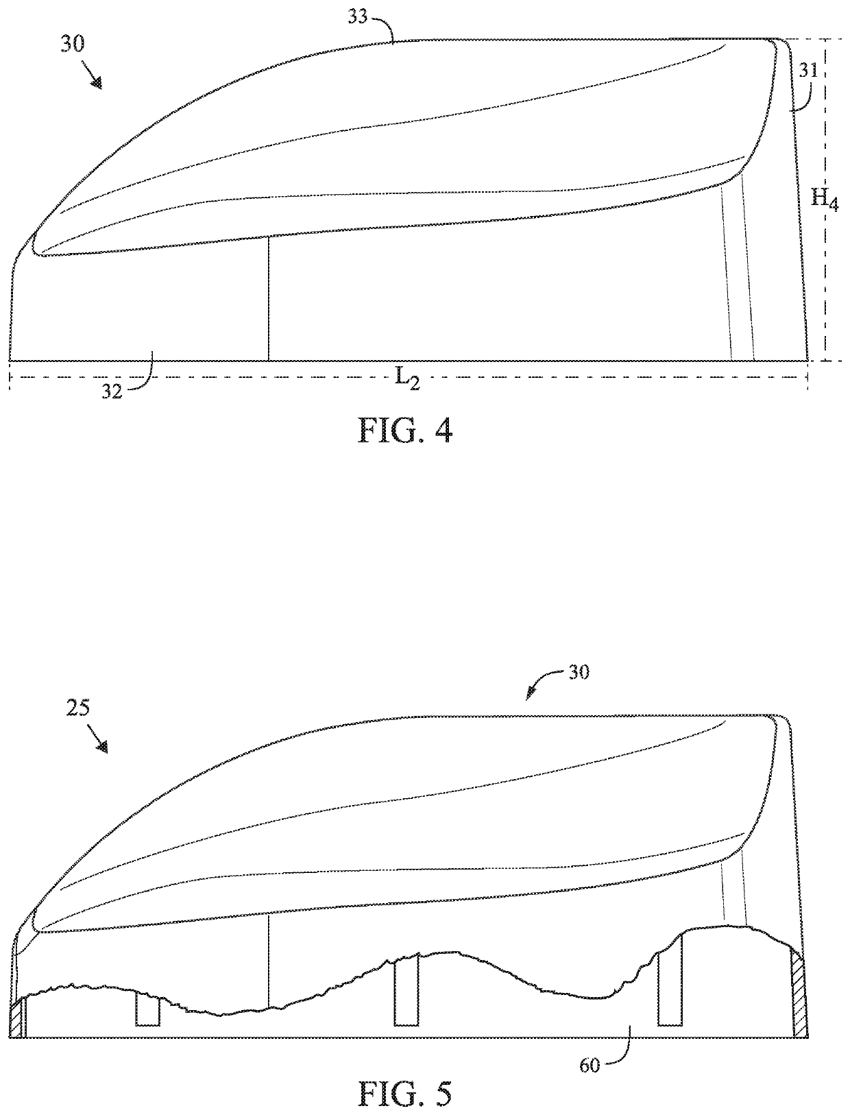
[0029]An antenna assembly 25 is shown in FIG. 1. The antenna assembly preferably comprises a base 60, a modem 50, a top lid 40 and a housing 30. The base 60 is preferably composed of an aluminum material. The modem 50 is disposed on the base 60. The top lid 40 is to cover the base 60 and modem 50, and the top lid 40 preferably comprises at least one antenna element disposed on an exterior surface. A radiofrequency cable 70 is attached to the modem 50 and secured to the base 60 by bolt 71. The housing 30 covers the top lid 40 and the base 60. The top lid 40 acts as an electro-magnetic barrier for the modem 50 to maintain the electro-magnetic signals inside of the base 60 to prevent interference with the antenna signals.

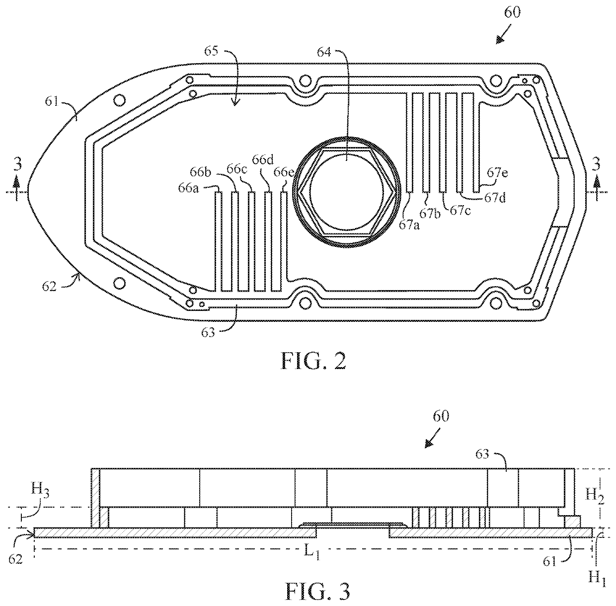
[0030]As shown in FIGS. 2 and 3, the base 60 includes a body 61 with an interior surface 62. A side wall 63 defines an interior compartment 65 in which a first plurality of heat dissipation elements 66a-66e and a second plurality of heat dissipation elements 67a-67e. A...


PUM


Abstract

An antenna assembly comprising a base, a modem, a top lid and a housing is disclosed herein. The antenna assembly is for a vehicle. The base is composed of an aluminum material. The modem is disposed within the base. The top lid is for the base, and the top lid comprises at least one antenna element disposed on an exterior surface thereof. The housing covers the top lid and base. The top lid and base act as an electro-magnetic barrier for the modem.

Description

CROSS REFERENCE TO RELATED APPLICATION[0001]Not ApplicableSTATEMENT REGARDING FEDERALLY SPONSORED RESEARCH OR DEVELOPMENT[0002]Not ApplicableBACKGROUND OF THE INVENTIONField of the Invention[0003]This invention relates to antenna assemblies for vehicles.Description of the Related Art[0004]In wireless communication systems for vehicles, a modem for the vehicle is typically placed a great distance away from an antenna in order to prevent electro-magnetic signals from the modem from interfering with the antenna. This often requires a long coaxial cable wired throughout the vehicle.[0005]General definitions for terms utilized in the pertinent art are set forth below.[0006]BLUETOOTH technology is a standard short range radio link that operates in the unlicensed 2.4 gigahertz band.[0007]Code Division Multiple Access (“CDMA”) is a spread spectrum communication system used in second generation and third generation cellular networks, and is described in U.S. Pat. No. 4,901,307.[0008]GSM, Glo...

Claims


Application Information

Patent Timeline
Patent Type & Authority Patents(United States)
IPC IPC(8): H01Q1/32H05K1/02H01Q1/22H01Q1/02H01Q1/24
CPCH01Q1/241H01Q1/2291H01Q1/02H01Q1/3275H05K1/0216H05K1/0203H01Q21/28
Inventor THILL, KEVIN
Owner AIRGAIN INC
Why Eureka
Try Eureka