Magnetic circuit structure of brushless DC motor and embedded rotor of permanent magnet of magnetic circuit structure

A brushless DC motor and permanent magnet technology, applied in the shape/style/structure of the magnetic circuit, the rotating parts of the magnetic circuit, the magnetic circuit, etc., can solve the magnetic field interference of the Hall position sensor stator and affect the smooth operation and work efficiency of the motor , Hall position sensor stator high temperature effects and other issues, to improve the Hall signal jitter phenomenon, improve smoothness and reliability, and save materials

Inactive Publication Date: 2015-04-29
HAMMER ELECTRIC POWER TOOLS
View PDF9 Cites 10 Cited by
  • Summary
  • Abstract
  • Description
  • Claims
  • Application Information

AI Technical Summary

Problems solved by technology

[0003] 1. The Hall position sensor is easily disturbed by the magnetic field of the stator, especially in high-power applications;
[0004] 2. When the embedded permanent magnet rotor is used, because the dividing line between the two magnetic poles of the rotor is not neat and clear, it is easy to cause the Hall signal to jitter, which in turn affects the smooth operation and working efficiency of the motor;
[0005] 3. The Hall position sensor is easily affected by the high temperature of the stator, especially in high-power applications;
However, there is a sudden change in the magnetic circuit structure in the magnetic separation air gap ω and the edge distance b of the existing permanent magnet embedded rotor, such as Figure 9 and Figure 10 As shown, it will cause local magnetic density flow direction and sudden change of magnetic density, which will lead to

Method used


Image

  • Magnetic circuit structure of brushless DC motor and embedded rotor of permanent magnet of magnetic circuit structure
  • Magnetic circuit structure of brushless DC motor and embedded rotor of permanent magnet of magnetic circuit structure
  • Magnetic circuit structure of brushless DC motor and embedded rotor of permanent magnet of magnetic circuit structure

Examples


Embodiment Construction

[0046] In order to better understand the above technical solutions of the present invention, a further detailed description will be given below in conjunction with the drawings and embodiments.

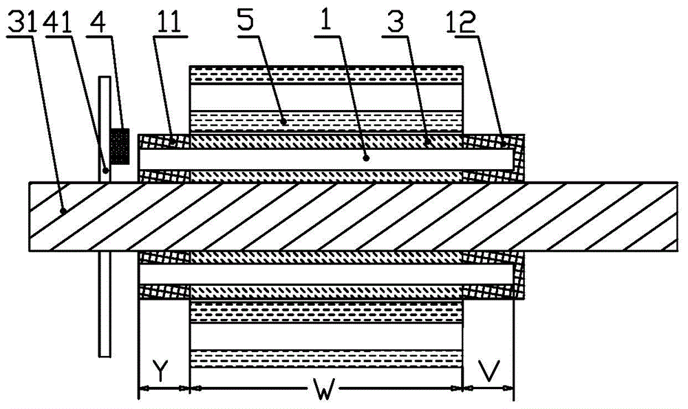
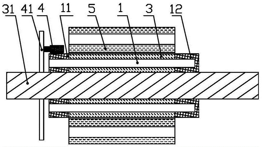
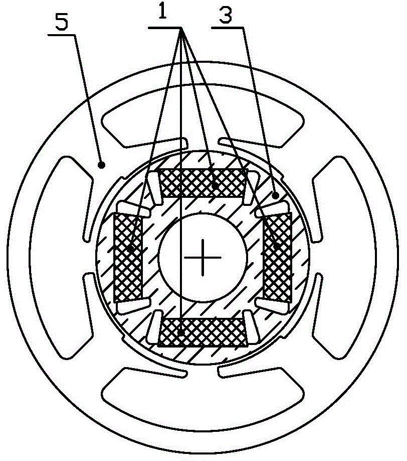
[0047] An example of the magnetic circuit structure of the DC brushless motor of the present invention is figure 1 As shown, it includes a stator core 5, a rotor core 3 laminated by rotor punches 30, a permanent magnet 1 embedded in the rotor core 3, and a magnet for detecting changes in the rotor magnetic field to realize commutation control. sensitive sensor 4; the length of the rotor core 3 is consistent with the length of the stator core 5, figure 1 Marked with W;

[0048] The length of the permanent magnet 1 is greater than the length of the rotor core 3, and at least one end of the permanent magnet 1 protrudes from the end face of the rotor core 3 to form an extension of the permanent magnet 1. figure 1 Indicated by the protruding length Y and V;

[0049] The magnetic sens...


PUM


Abstract

The invention relates to a magnetic circuit structure of a brushless DC motor and an embedded rotor of a permanent magnet of the magnetic circuit structure and relates to a motor which is provided with a non-mechanical reversing device and a magnetic circuit part of the motor, in particular to a brushless DC motor which applies a magnetic effect device and a magnetic circuit part structure which is provided with the embedded rotor of the permanent magnet. The magnetic circuit structure comprises a stator iron core, a rotor iron core, a permanent magnet and a magneto-dependent sensor, wherein the length of the permanent magnet is greater than that of the rotor iron core, the magneto-dependent sensor is arranged in a position which is close to an extension part of the rotor iron core and far from magnetic field interference of the stator, magnetic barriers and positioning bumps for fixing the permanent magnet are arranged at two ends of a permanent magnet groove, and the magneto-dependent sensor induces the end magnetic field of the permanent magnet rather than a combined magnetic field of the rotor iron core and the permanent magnet, so that hall signal jitter caused by an irregular and clear boundary between two magnetic poles on the surface of the rotor is effectively reduced; according to the improved structure, the magneto-dependent sensor is far from influence of the stator magnetic field and temperature, so that the operating smoothness and reliability of motor are further improved.

Description

technical field [0001] The invention relates to a motor with a non-mechanical reversing device and its magnetic circuit components, in particular to a DC brushless motor with a magnetic effect device and the magnetic circuit component structure of a permanent magnet embedded rotor. Background technique [0002] The basic structure of a brushless DC motor is composed of an electronic switch commutation device, a permanent magnet synchronous motor and a position sensor. The position sensor converts the position of the rotor magnet into an electrical signal to control the electronic switch commutation device, so that the stator phase The current commutates in the correct order as the rotor position changes. Only in this way can the electronic magnetic field change continuously with the rotation of the rotor, generate a rotating magnetic field synchronous with the rotor speed, and push the rotor to rotate with the maximum torque. The most commonly used position sensor for brush...

Claims


Application Information

Patent Timeline
IPC IPC(8): H02K29/03H02K29/08H02K1/27
CPCH02K1/274H02K29/03H02K29/08
Inventor 王科威温瑞光
Owner HAMMER ELECTRIC POWER TOOLS
Why Eureka
Try Eureka