Wire rope flaw detection device

a flaw detection and wire rope technology, applied in the direction of material magnetic variables, lifters, transportation and packaging, etc., can solve the problem of leakage flux occurring in the periphery of a damaged part, and achieve the effect of amplifying the peak of induced voltage and improving the s/n ratio more positively

Active Publication Date: 2019-12-24
MITSUBISHI ELECTRIC CORP
View PDF12 Cites 2 Cited by
  • Summary
  • Abstract
  • Description
  • Claims
  • Application Information

AI Technical Summary

Benefits of technology

[0013]In the wire rope flaw detector according to the present invention, the voltage waveforms of the plurality of search coils are superimposed on each other while the voltage waveforms are shifted by the time calculated based on the interval between the plurality of search coils adjacent to each other and on the relative moving speed of the wire rope with respect to the magnetizer, to thereby amplify the peak of the induced voltage. Thus, the S / N ratio can be improved more positively.

Problems solved by technology

In a case where damage has been caused to the wire rope, a leakage flux occurs in a periphery of a damaged part when the damaged part enters the magnetized segment.

Method used


Image

  • Wire rope flaw detection device
  • Wire rope flaw detection device
  • Wire rope flaw detection device

Examples


first embodiment

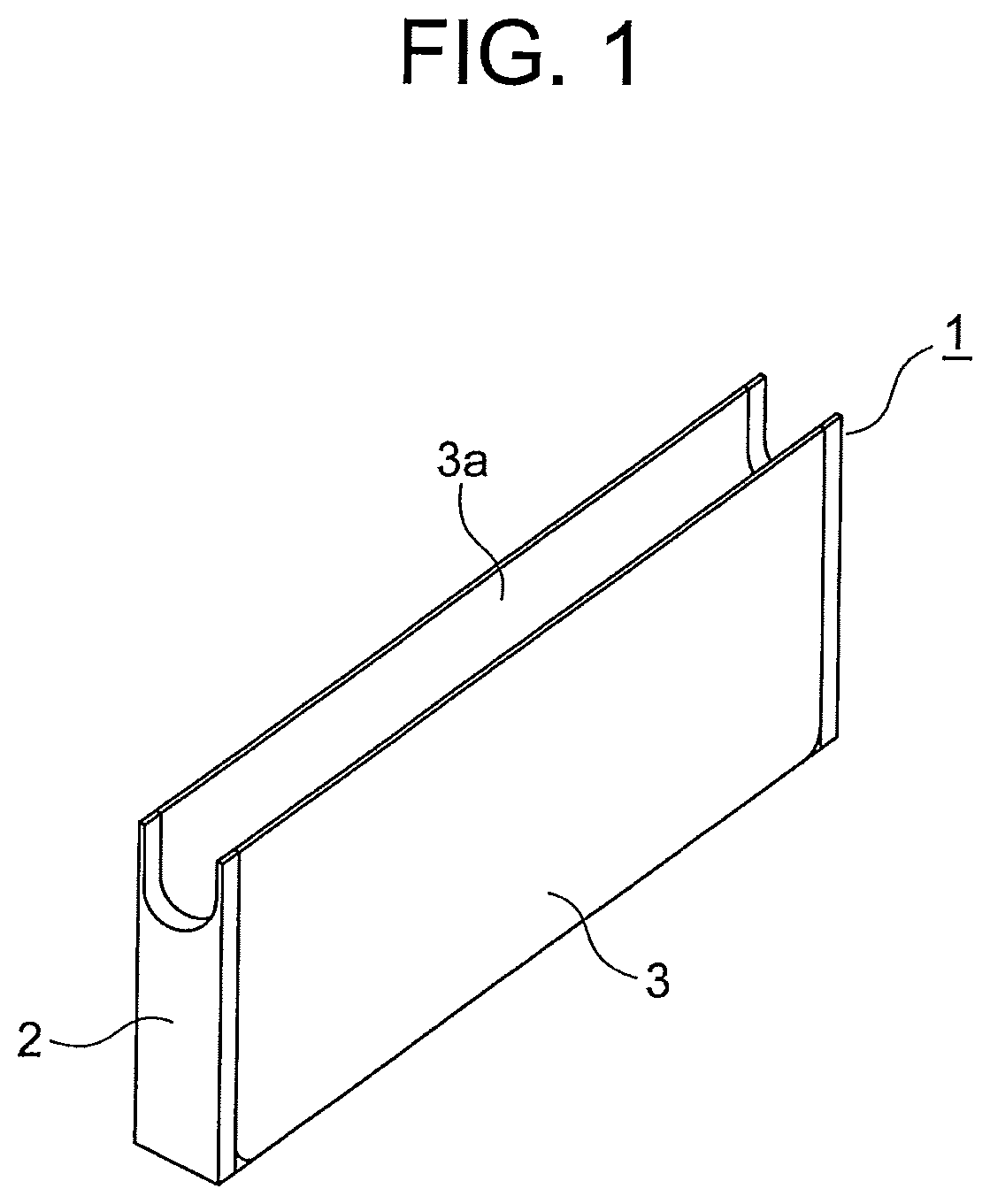
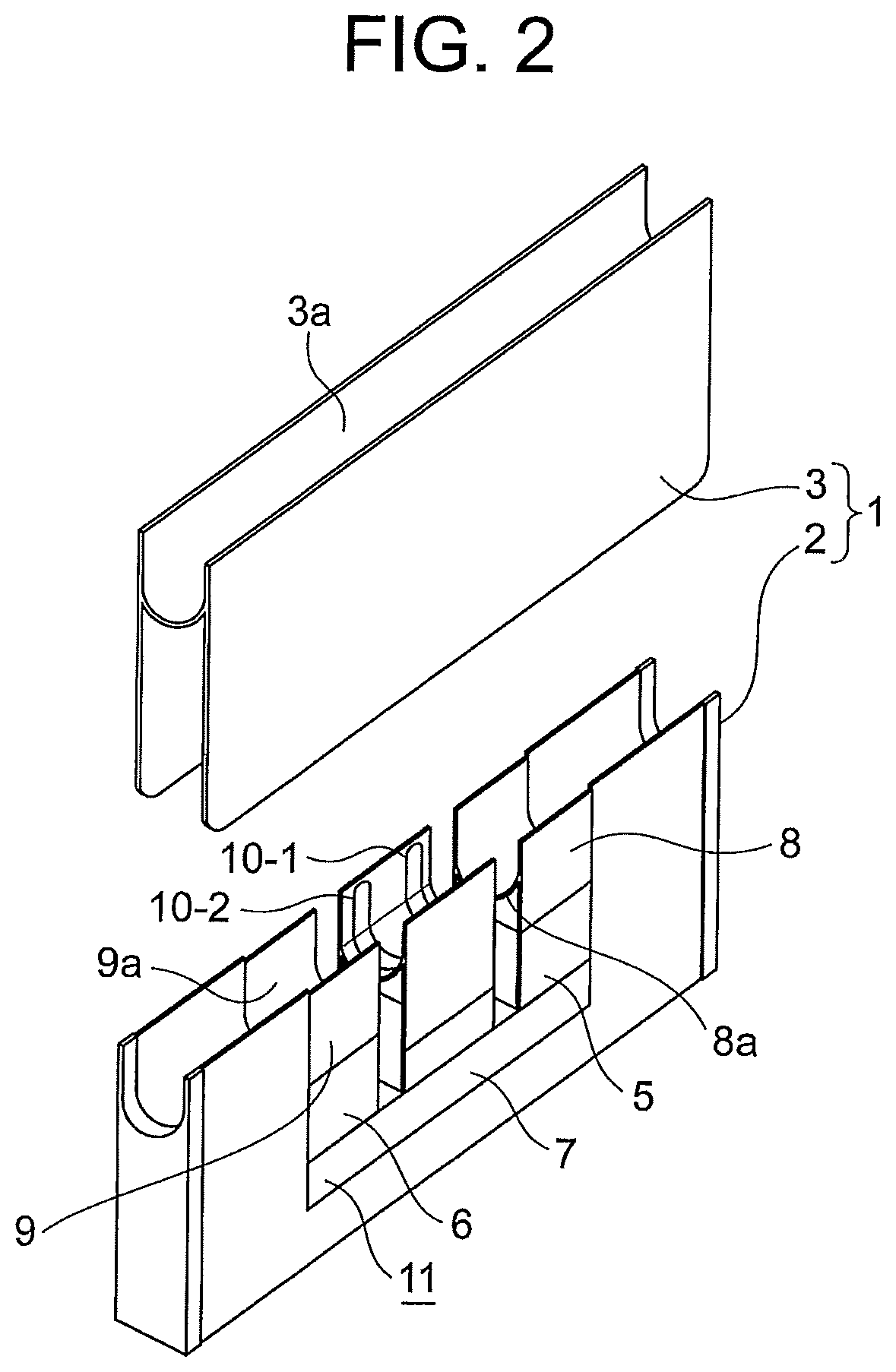
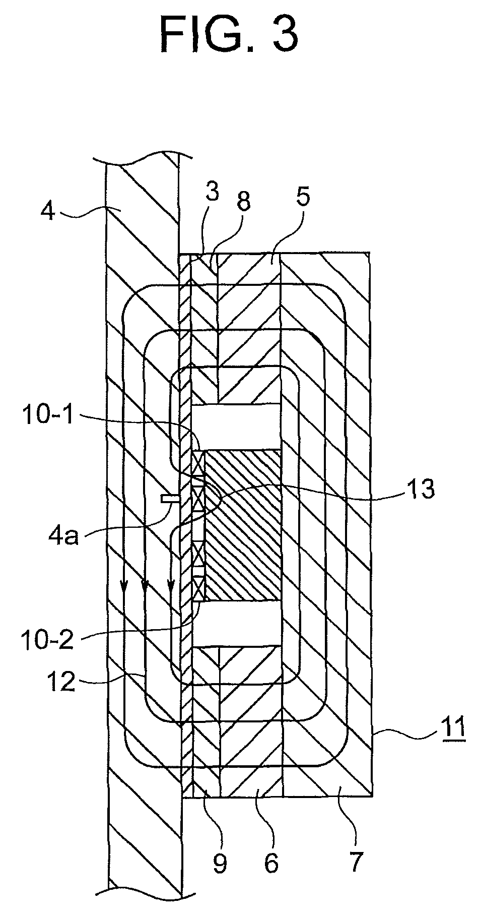
[0026]FIG. 1 is a perspective view for illustrating a probe of a wire rope flaw detector according to a first embodiment of the present invention, and FIG. 2 is a perspective view for illustrating the probe by decomposing a part of the probe of FIG. 1. In the figures, a case 1 includes a case main body 2 and a cover 3 configured to cover the case main body 2 to protect components provided inside the probe. The cover 3 is provided with a cover groove portion 3a having a U-shaped section. A wire rope 4 (FIG. 3) is guided to an inside of the cover groove portion 3a, and is moved relatively with respect to the probe while kept in contact with the cover 3.

[0027]The case main body 2 includes a first permanent magnet 5, a second permanent magnet 6, a back yoke 7, a first pole piece 8, a second pole piece 9, a first search coil 10-1, and a second search coil 10-2. The first permanent magnet 5 and the second permanent magnet 6 are arranged with an interval so as to be spaced apart from each ...

second embodiment

[0044]Next, FIG. 6 is a configuration diagram for illustrating a main part of a wire rope flaw detector according to a second embodiment of the present invention. The specifications of components of the probe for magnetizing the wire rope 4, namely, the first permanent magnet 5, the second permanent magnet 6, the back yoke 7, the first pole piece 8, and the second pole piece 9, are the same as those of the first embodiment.

[0045]The second embodiment is different from the first embodiment in the signal processing method. In this embodiment, the first search coil 10-1 and the second search coil 10-2 are connected to each other in series. A difference between a potential at one end of the first search coil 10-1 and a potential at one of the second search coil 10-2 is A / D-converted in the subsequent stage to be stored in the FIFO buffer of the control unit 21 as output that combines the two search coils 10-1 and 10-2.

[0046]FIG. 7 is an explanatory diagram for illustrating the waveform ...

third embodiment

[0095]Next, FIG. 10 is a configuration diagram for illustrating a main part of a wire rope flaw detector according to a third embodiment of the present invention, and FIG. 11 is an explanatory diagram for illustrating the waveform processing method performed by the control unit 21 of FIG. 10. This embodiment is achieved by generalizing the superimposition of signals described in the second embodiment with the number of search coils being set to m (m is an integer equal to or larger than 3). That is, first to m-th search coils 10-1 to 10-m are arranged in the probe at a regular interval P.

[0096]Those search coils 10-1 to 10-m are connected to one another in series, and generate m peak waveforms while one damaged part 4a passes through the probe. The peak is emphasized by superimposing those peaks m−1 times with an interval of the time period τ. Now, assuming that all the search coils 10-1 to 10-m are wound in the same direction and connected to one another in an in-phase direction, i...


PUM

PropertyMeasurementUnit
magnetic fluxaaaaaaaaaa
voltagesaaaaaaaaaa
voltageaaaaaaaaaa

Abstract

Provided is a wire rope flaw detector including a magnetizer configured to form a main magnetic flux in a part of a wire rope in a longitudinal direction thereof. A plurality of search coils are configured to detect a leakage flux that occurs from a damaged part of the wire rope in a segment in which the main magnetic flux is formed. A control unit is configured to detect induced voltages generated in the plurality of search coils. Further, the control unit is configured to superimpose voltage waveforms of the plurality of search coils on one another while shifting the voltage waveforms by a time calculated based on an interval between the plurality of search coils adjacent to each other and on a relative moving speed of the wire rope with respect to the magnetizer, to thereby amplify a peak of the induced voltage.

Description

TECHNICAL FIELD[0001]The present invention relates to a wire rope flaw detector configured to detect breakage of a wire rope, for example, a wire rope for suspending a car of an elevator or a wire rope used for a crane, and a break in an element wire of the wire rope, namely, damage to the element wire.BACKGROUND ART[0002]In general, for a wire rope used for an elevator, a crane, or the like, it is periodically checked whether or not a break exists in an element wire. When a large number of element wires are broken, the wire rope is replaced. Such inspection is performed by visual observation as a rule, but a wire rope flaw detector may be used in order to improve work efficiency.[0003]The related-art wire rope flaw detector includes a magnetizer and a coil portion serving as a magnetic sensor. The magnetizer includes a first permanent magnet and a second permanent magnet, which are arranged with an interval so as to be spaced apart from each other, and a back yoke configured to joi...

Claims


Application Information

Patent Timeline
Patent Type & Authority Patents(United States)
IPC IPC(8): G01N27/87
CPCG01N27/87G01N27/83G01N27/82B66B7/1215
Inventor YOSHIOKA, TAKASHIKOTERA, TAKAYUKIHIROTA, KAZUAKIHOSHINOO, TOMOKAZUTAKAHASHI, FUMITAKEAKASHI, MASAOSEKI, TETSURO
Owner MITSUBISHI ELECTRIC CORP
Why Eureka
Try Eureka