Check patentability & draft patents in minutes with Patsnap Eureka AI!

Method employed in LDPC decoder and the decoder

a low-density parity check and decoder technology, applied in the field of decoding mechanisms, can solve the problems of slow convergence, complexity computation of flipping schemes, etc., and achieve the effects of improving the performance of the decoder, reducing the complexity of computation, and speeding up convergen

Active Publication Date: 2019-12-31
SILICON MOTION INC (TW)
View PDF4 Cites 4 Cited by
  • Summary
  • Abstract
  • Description
  • Claims
  • Application Information

AI Technical Summary

Benefits of technology

[0006]According to the embodiments mentioned above, the method and decoder can significantly improve the performance of the decoder, reduce the complexity of computation, and speed up the convergence.

Problems solved by technology

This conventional bit flipping scheme inevitably needs complexity computation and leads to a slow convergence problem since it is necessary for the conventional scheme to calculate all preliminary / initial syndromes of all data bits of a complete codeword, then determining the flipping threshold based on all the preliminary / initial syndromes which have been calculated, and finally deciding whether to flip / toggle each bit of the complete codeword according to such flipping threshold and the calculated syndromes of all bits.

Method used


Image

  • Method employed in LDPC decoder and the decoder
  • Method employed in LDPC decoder and the decoder
  • Method employed in LDPC decoder and the decoder

Examples


first embodiment

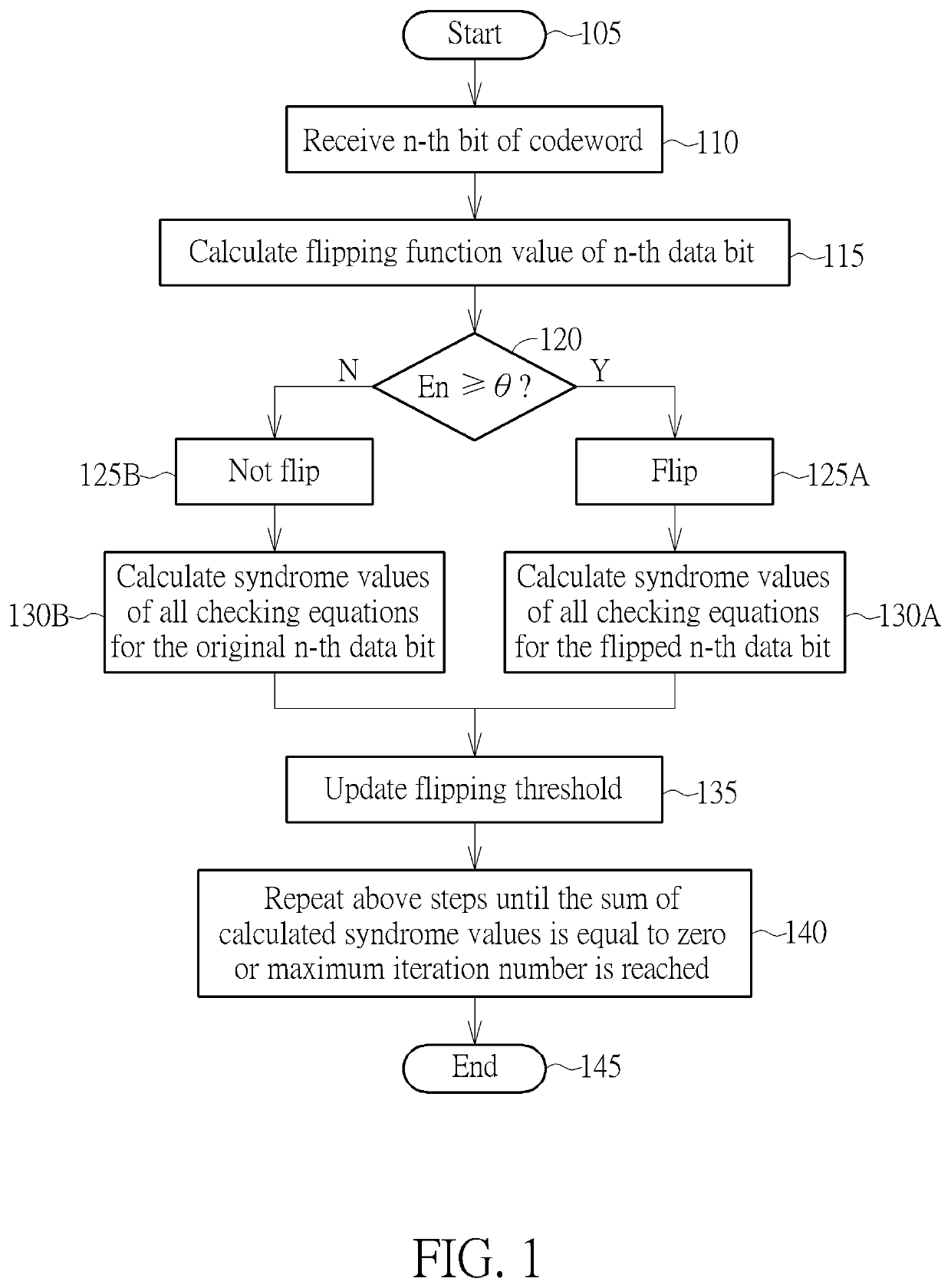
[0012]FIG. 1 is a diagram showing a flowchart of a decoding method employed in a linear block code decoder such as a low-density parity-check (LDPC) code decoder according to the invention. Some data portions such as data bit(s) included in a codeword during transmission may be altered by some errors, and the decoding method is arranged to receive and decode such codeword to generate a correct codeword. The decoding method is arranged to perform a flipping operation which is used for determining whether to flip a data portion such as a bit (but not limited) of the received codeword and then calculate a corresponding syndrome after the flipping operation. If the calculated corresponding syndrome is equal to zero, the bit (flipped or not flipped) is estimated as a correct bit. That is, the decoding method correctly decodes this bit. The flipping operation is performed for each data portion such as each data bit of each codeword.

[0013]For a complete codeword, a conventional scheme is a...

second embodiment

[0037]Further, the decoding method mentioned above can be also applied to a weighted bit flipping (WBF) decoder circuit. Please refer to FIG. 3 in conjunction with FIG. 4. FIG. 3 is a diagram showing a flowchart of a decoding method employed in a WBF LDPC decoder according to the invention. FIG. 4 is a block diagram of a WBF LDPC decoder circuit 400 according to the embodiment of FIG. 3. In the embodiment, the method employed in the WBF decoder circuit 400 can be further arranged to determine weighted values based on information of syndrome / checking values of the previous data bits to determine flipping function values and flipping threshold.

[0038]Provided that substantially the same result is achieved, the steps of the flowchart shown in FIG. 3 need not be in the exact order shown and need not be contiguous, that is, other steps can be intermediate. Steps are detailed in the following:

[0039]Step 305: Start;

[0040]Step 307: Calculate initial weighting;

[0041]Step 310: Receive a specif...


PUM


Abstract

A method employed in a low-density parity-check code decoder includes: receiving a specific data portion of a first codeword; calculating a flipping function value of the specific data portion of the first codeword according to the specific data portion by using checking equations of a parity check matrix to calculate checking values of the specific data portion; and determining whether to flip the specific data portion of the first codeword by comparing the flipping function value with a flipping threshold which has been calculated based on a plurality of flipping function values of a plurality of previous data portions earlier than the specific data portion.

Description

BACKGROUND OF THE INVENTION1. Field of the Invention[0001]The invention relates to a decoding mechanism, and more particularly to a method employed in a low-density parity-check code (LDPC) decoder and the LDPC decoder.2. Description of the Prior Art[0002]Generally speaking, an LDPC decoder with a conventional bit flipping scheme is arranged to calculate all preliminary / initial syndromes of all data bits of a complete codeword, then determine a flipping threshold based on all the preliminary / initial syndromes, then respectively deciding whether to flip / toggle each bit of the complete codeword by comparing the calculated syndrome of the each bit with the flipping threshold, and calculating or updating the syndrome of each bit of the complete codeword if such bit has been flipped or toggled. This conventional bit flipping scheme inevitably needs complexity computation and leads to a slow convergence problem since it is necessary for the conventional scheme to calculate all preliminary...

Claims


Application Information

Patent Timeline
Patent Type & Authority Patents(United States)
IPC IPC(8): H03M13/11H03M13/00
CPCH03M13/1108H03M13/1128H03M13/616
Inventor KUO, SHIUAN-HAO
Owner SILICON MOTION INC (TW)
Features
  • R&D
  • Intellectual Property
  • Life Sciences
  • Materials
  • Tech Scout
  • Unparalleled Data Quality
  • Higher Quality Content
  • 60% Fewer Hallucinations
Learn More