
Induction-based aerosol delivery device

a technology of aerosol and induction, which is applied in the direction of electric/magnetic/electromagnetic heating, tobacco, batteries, etc., can solve the problems of adding potential failure points, delivering large quantities of incomplete combustion and pyrolysis products, and complicating the assembly of the aerosol delivery devi

Active Publication Date: 2020-01-07
RAI STRATEGIC HLDG INC
View PDF243 Cites 21 Cited by
  • Summary
  • Abstract
  • Description
  • Claims
  • Application Information

AI Technical Summary

Benefits of technology

The present patent relates to aerosol delivery devices, such as electronic cigarettes or heat-not-burn cigarettes, that produce aerosol by heating an aerosol precursor composition using a resonant transformer and a pulse width modulation (PWM) inverter. The technical effects of the patent include the ability to produce aerosol without needing a physical electrical connection between the aerosol delivery device and the power source, and the use of a resonant transformer and PWM inverter to efficiently heat the aerosol precursor composition. The patent also describes various methods for controlling the operation of the aerosol delivery device, including the use of a control body and a high-pass filter to filter out direct voltage components. Overall, the patent provides technical means for improving the efficiency and control of aerosol delivery devices.

Problems solved by technology

Many of those devices purportedly have been designed to provide the sensations associated with cigarette, cigar, or pipe smoking, but without delivering considerable quantities of incomplete combustion and pyrolysis products that result from the burning of tobacco.
However, forming such electrical connections may complicate assembly of the aerosol delivery device and add potential points of failure.
In these implementations electrical connections between the cartridge and the control body may be required, which may further complicate the design of the aerosol delivery device.

Method used


Image

  • Induction-based aerosol delivery device
  • Induction-based aerosol delivery device
  • Induction-based aerosol delivery device

Examples


Embodiment Construction

[0043]The present disclosure will now be described more fully hereinafter with reference to example implementations thereof. These example implementations are described so that this disclosure will be thorough and complete, and will fully convey the scope of the disclosure to those skilled in the art. Indeed, the disclosure may be embodied in many different forms and should not be construed as limited to the implementations set forth herein; rather, these implementations are provided so that this disclosure will satisfy applicable legal requirements. As used in the specification and the appended claims, the singular forms “a,”“an,”“the” and the like include plural referents unless the context clearly dictates otherwise. Also, while reference may be made herein to quantitative measures, values, geometric relationships or the like, unless otherwise stated, any one or more if not all of these may be absolute or approximate to account for acceptable variations that may occur, such as th...


PUM

PropertyMeasurementUnit
magnetic fieldaaaaaaaaaa
constant voltageaaaaaaaaaa
poweraaaaaaaaaa

Abstract

An aerosol delivery device is provided that includes a substrate configured to carry an aerosol precursor composition, and a resonant transformer including a transmitter coupling device and a resonant receiver coupling device that is positioned in proximity to the substrate. The aerosol delivery device also includes a pulse width modulation (PWM) inverter configured to drive the resonant transformer. The PWM inverter includes a bridge circuit coupled to the transmitter coupling device, and a PWM controller embodied as an integrated circuit and configured to output a PWM signal to the bridge circuit configured to drive the transmitter coupling device to generate an oscillating magnetic field and induce an alternating voltage in the resonant receiver coupling device when exposed to the oscillating magnetic field. The alternating voltage causes the resonant receiver coupling device to generate heat and thereby vaporize components of the aerosol precursor composition.

Description

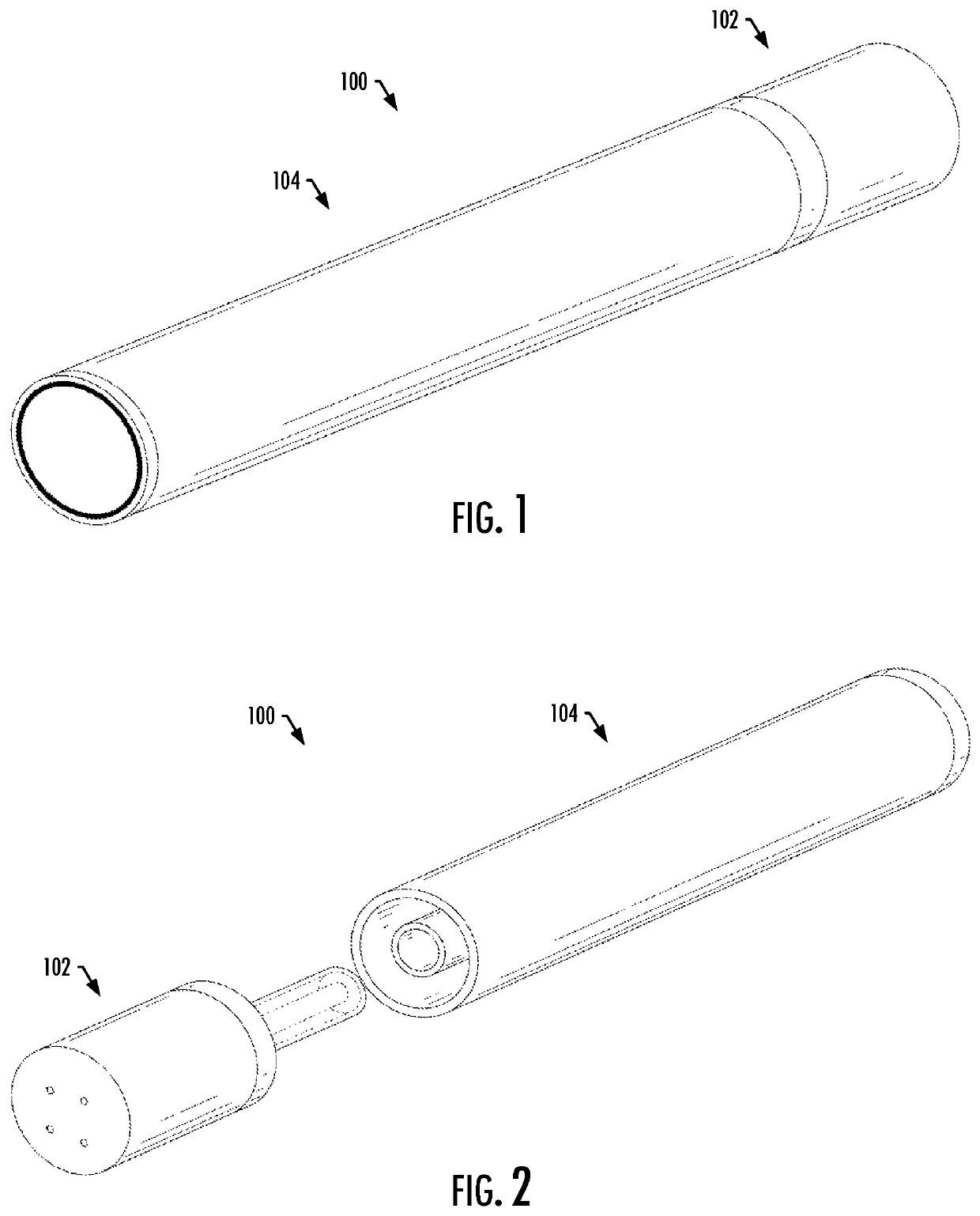
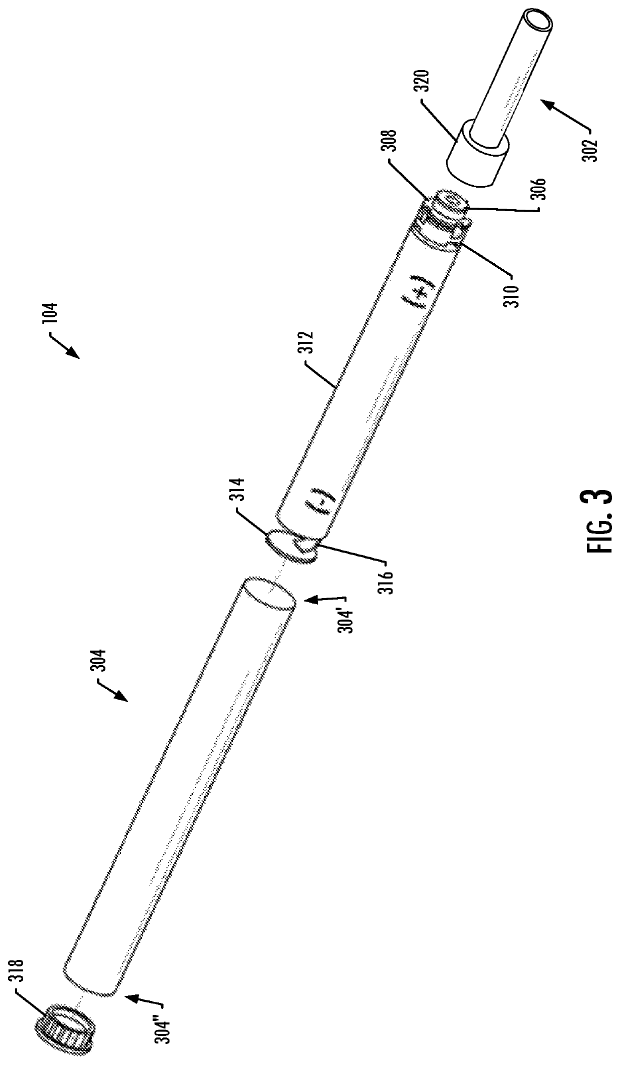
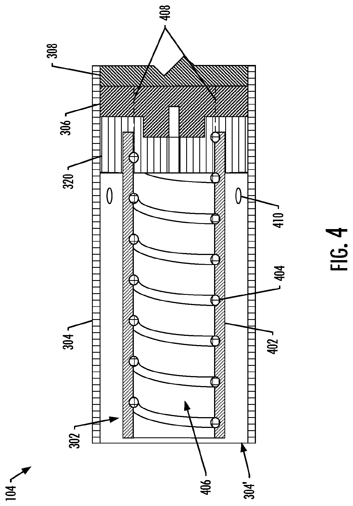
TECHNOLOGICAL FIELD[0001]The present disclosure relates to aerosol delivery devices such as smoking articles, and more particularly to aerosol delivery devices that may utilize electrically generated heat for the production of aerosol (e.g., smoking articles commonly referred to as electronic cigarettes). The smoking articles may be configured to heat an aerosol precursor, which may incorporate materials that may be made or derived from, or otherwise incorporate tobacco, the precursor being capable of forming an inhalable substance for human consumption.BACKGROUND[0002]Many devices have been proposed through the years as improvements upon, or alternatives to, smoking products that require combusting tobacco for use. Many of those devices purportedly have been designed to provide the sensations associated with cigarette, cigar, or pipe smoking, but without delivering considerable quantities of incomplete combustion and pyrolysis products that result from the burning of tobacco. To th...

Claims


Application Information

Patent Timeline
Patent Type & Authority Patents(United States)
IPC IPC(8): A24F47/00H01G11/06H05B1/02H01M10/0525A61M15/06A24F40/465A24F40/50A24F40/90
CPCH01M10/0525H05B1/0244A24F47/008H01G11/06H01M2220/30H05B2206/024A24F40/40A24F40/50A24F40/465A24F40/51A24F40/90A61M11/042H02J50/12H05B6/108H02J7/00045Y02E60/10A24F40/10A24F40/65A24F40/95A61M2205/8206H02J50/10A24F40/20A24F40/57A61M2205/3317A61M2205/3334A61M2205/50A61M2205/8243H02M7/53871
Inventor SUR, RAJESHROGERS, JAMES W.SEARS, STEPHEN B.HUNT, ERIC T.
Owner RAI STRATEGIC HLDG INC
Learn More