Series regulator including parallel transistors

a technology of parallel transistors and regulators, applied in the direction of electric variable regulation, process and machine control, instruments, etc., can solve the problems of difficult to achieve stable operation in a wide load range and fast load response, and achieve stable operation and fast load response , the effect of wide load rang

Active Publication Date: 2020-01-14
ROHM CO LTD
View PDF10 Cites 1 Cited by
  • Summary
  • Abstract
  • Description
  • Claims
  • Application Information

AI Technical Summary

Benefits of technology

[0009]In view of the above-mentioned problem encountered by the present inventors, it is an object of the invention disclosed herein to provide a series regulator (of which an LDO [low drop-out] regulator is one type) which can achieve stable operation in a wide load range and fast load response combined with low current consumption.

Problems solved by technology

Thus, it is difficult to achieve stable operation in a wide load range and fast load response combined with low current consumption.

Method used


Image

  • Series regulator including parallel transistors
  • Series regulator including parallel transistors
  • Series regulator including parallel transistors

Examples


first embodiment

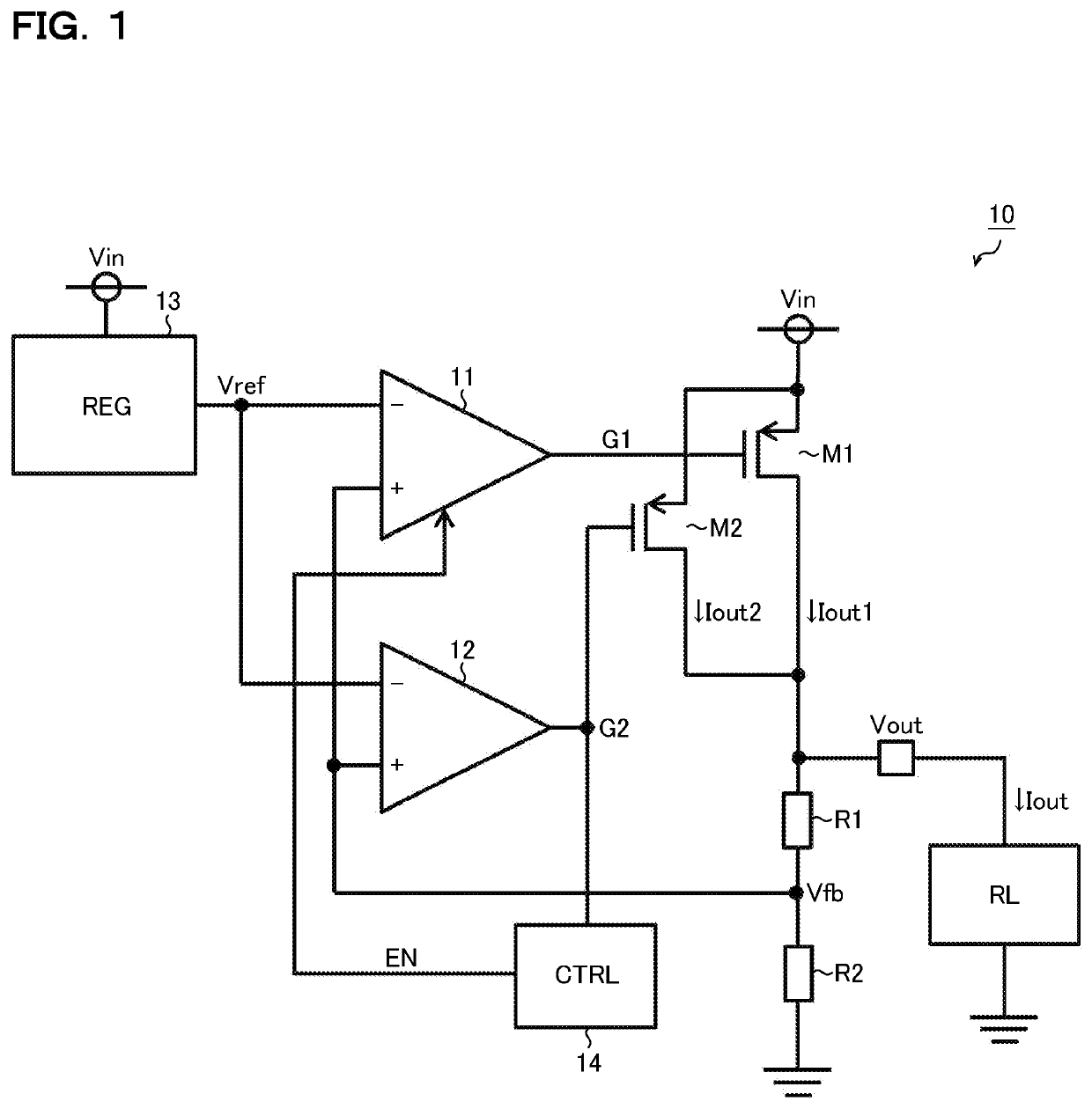
[0031]FIG. 1 is a diagram showing a series regulator according to a first embodiment. The series regulator 10 of this embodiment is a semiconductor integrated circuit device (series power supply IC) that includes operational amplifiers 11 and 12, a reference voltage source 13, an amplifier control circuit 14, p-channel MOS (metal-oxide-semiconductor) field-effect transistors M1 and M2, and registers R1 and R2. The series regulator 10 generates from an input voltage Vin a desired output voltage Vout (=[(R1+R2) / R2]×Vref) to feed it to a load RL.

[0032]Instead of being integrated into the semiconductor integrated circuit device, the transistors M1 and M2 and the resistors R1 and R2 may be configured as externally connected discrete parts.

[0033]The transistor M1 is an output transistor for a heavy load. The source of the transistor M1 is connected to a power source (that is, the input terminal of the input voltage Vin). The drain of the transistor M1 is connected to the load RL (that is,...

second embodiment

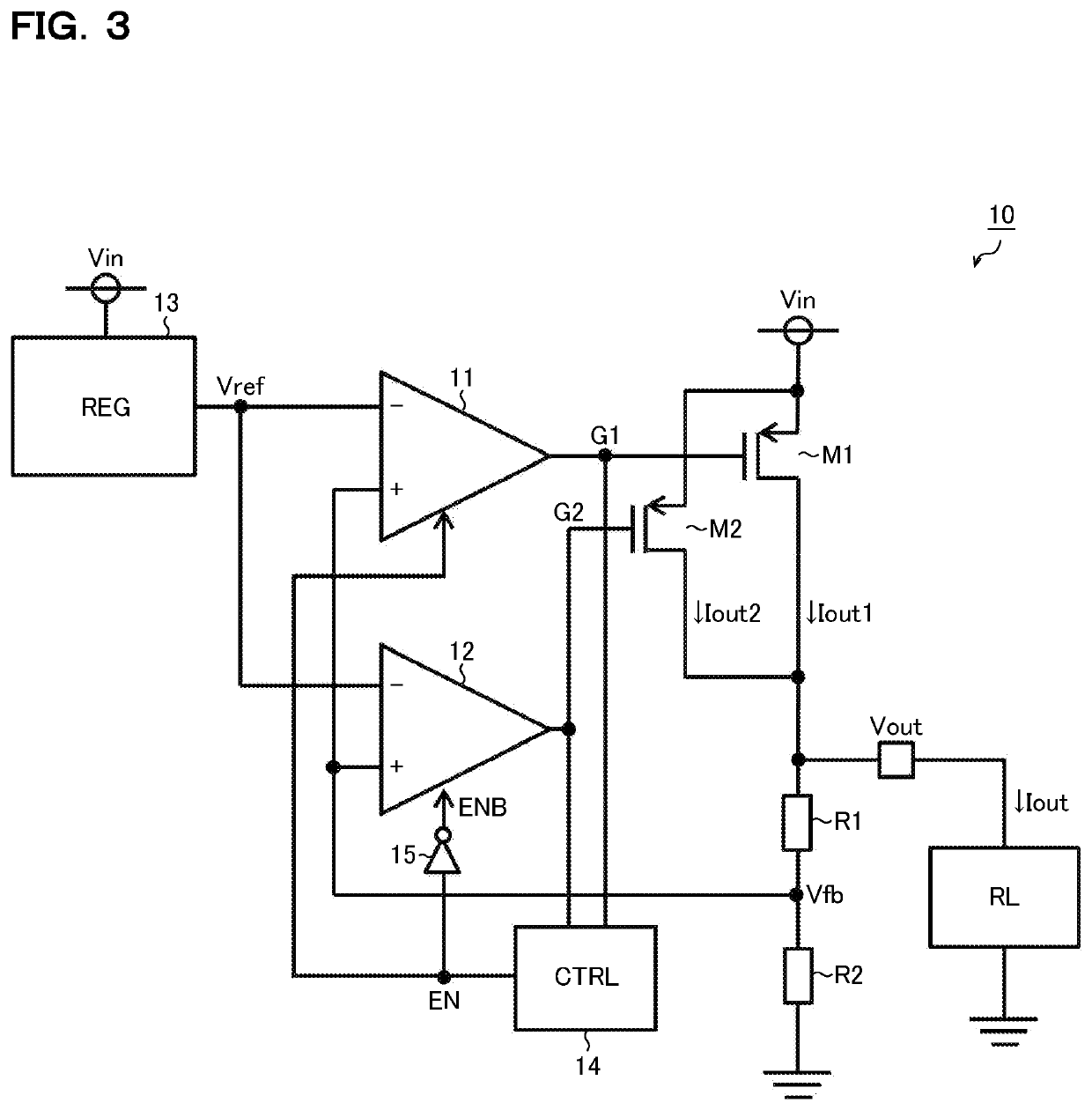
[0047]FIG. 3 is a diagram showing a series regulator according to a second embodiment. The series regulator 10 of this embodiment, while being based on the first embodiment (FIG. 1), is modified such that the amplifier control circuit 14 does not only control whether or not to operate the operational amplifier 11 but also controls whether or not to operate the operational amplifier 12. To achieve that, the series regulator additionally includes an inverter 15. Accordingly, such components as have already been mentioned are identified by the same reference signs as FIG. 1, and no overlapping description will be repeated. The following description focuses on features unique to this embodiment.

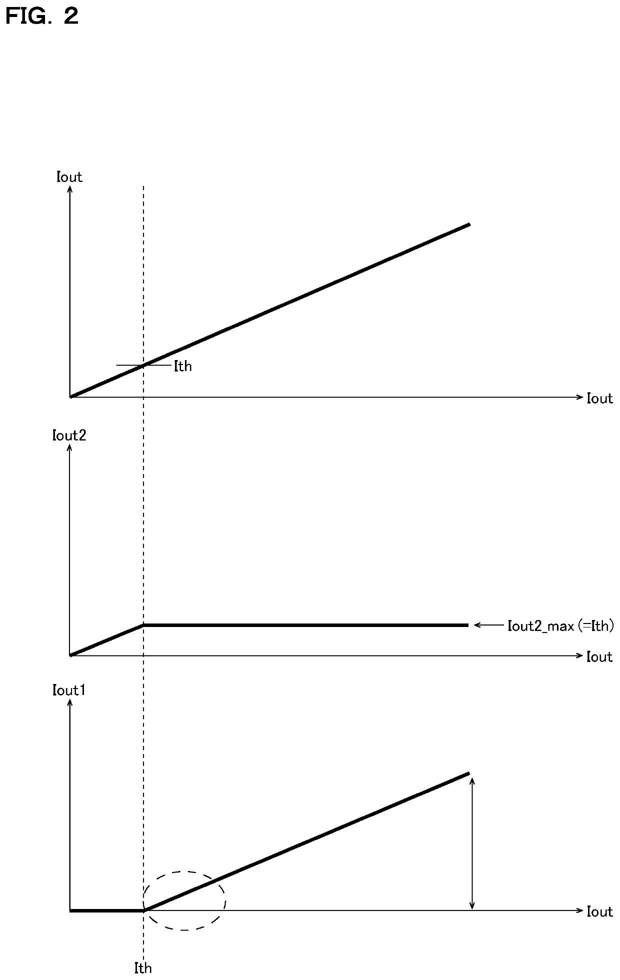
[0048]The amplifier control circuit 14 checks, for example based on both the gate signals G1 and G2, whether the output current Iout is in the light-load region (IoutIth). The amplifier control circuit 14 then, based on the check result, generates the enable signal EN. Specifically, the amplifier...

third embodiment

[0059]FIG. 5 is a diagram showing a series regulator according to a third embodiment. The series regulator 10 of this embodiment, while being based on the second embodiment (FIG. 3), is modified such that the operational amplifier 12 does not keep the transistor M2 completely off even in the heavy-load region. In this embodiment, the inverter 15 is omitted, and separate enable signals EN1 and EN2 are fed from the amplifier control circuit 14 to the operational amplifiers 11 and 12 respectively.

[0060]The amplifier control circuit 14 checks, for example based on the gate signal G2, whether the output current Iout is in the light-load region (IoutIth). The amplifier control circuit 14 then, based on the check result, generates the enable signals EN1 and EN2. Specifically, the amplifier control circuit 14 generates the enable signals EN1 and EN2 so as to keep the operational amplifiers 11 and 12, in the light-load region, in the disabled state and in the enabled state respectively and, ...


PUM


Abstract

A series regulator includes, for example, first and second operational amplifiers, for driving a first transistor for a heavy load and a second transistor for a light load respectively, and an amplifier control circuit. The amplifier control circuit controls the first and second operational amplifiers such that, in a light load region, a first output current passing through the first transistor has a zero value and a second output current passing through the second transistor covers the entire output current passing through a load, and such that, in a heavy load region, the second output current has a zero value (or a fixed value lower than an amplifier switching threshold value) and the first output current covers the entire output current (or a difference left by subtracting the second output current from the output current).

Description

CROSS-REFERENCE TO RELATED APPLICATIONS[0001]This application is based on the following Japanese Patent Application, the contents of which are hereby incorporated by reference:[0002](1) Japanese Patent Application published as No. 2018-070721, filed on Apr. 2, 2018BACKGROUND OF THE INVENTION[0003]1. Field of the Invention[0004]The invention disclosed herein relates to series regulators.[0005]2. Description of Related Art[0006]FIG. 17 is a diagram showing one example of a conventional series regulator. In the series regulator 20 of this conventional example, an operational amplifier 21 controls a gate signal G1 for an output transistor M1 so that a feedback voltage Vfb (a division voltage of an output voltage Vout) equals a reference voltage Vref. With this, it is possible to generate from an input voltage Vin a desired output voltage Vout (=[(R1+R2)] / R2)×Vref).[0007]One example of the conventional technology just mentioned is seen in Japanese Patent Application published as No. 2008...

Claims


Application Information

Patent Timeline
Patent Type & Authority Patents(United States)
IPC IPC(8): G05F1/565G05F1/59G05F1/575
CPCG05F1/565G05F1/575G05F1/59
Inventor YASUSAKA, MAKOTO
Owner ROHM CO LTD
Why Eureka
Try Eureka