Optics of wearable display devices

a technology of wearable display and optical fiber, which is applied in the field of optical fiber of wearable display devices, can solve the problems of not providing wearable display solutions that are satisfied by viewers, wearable displays often have low resolution, and the need for wearable displays is so great that it is easy to miss, minimize distortion, and increase the field of view

Active Publication Date: 2020-01-21
ISHII FUSAO MR +1
View PDF10 Cites 0 Cited by
  • Summary
  • Abstract
  • Description
  • Claims
  • Application Information

AI Technical Summary

Benefits of technology

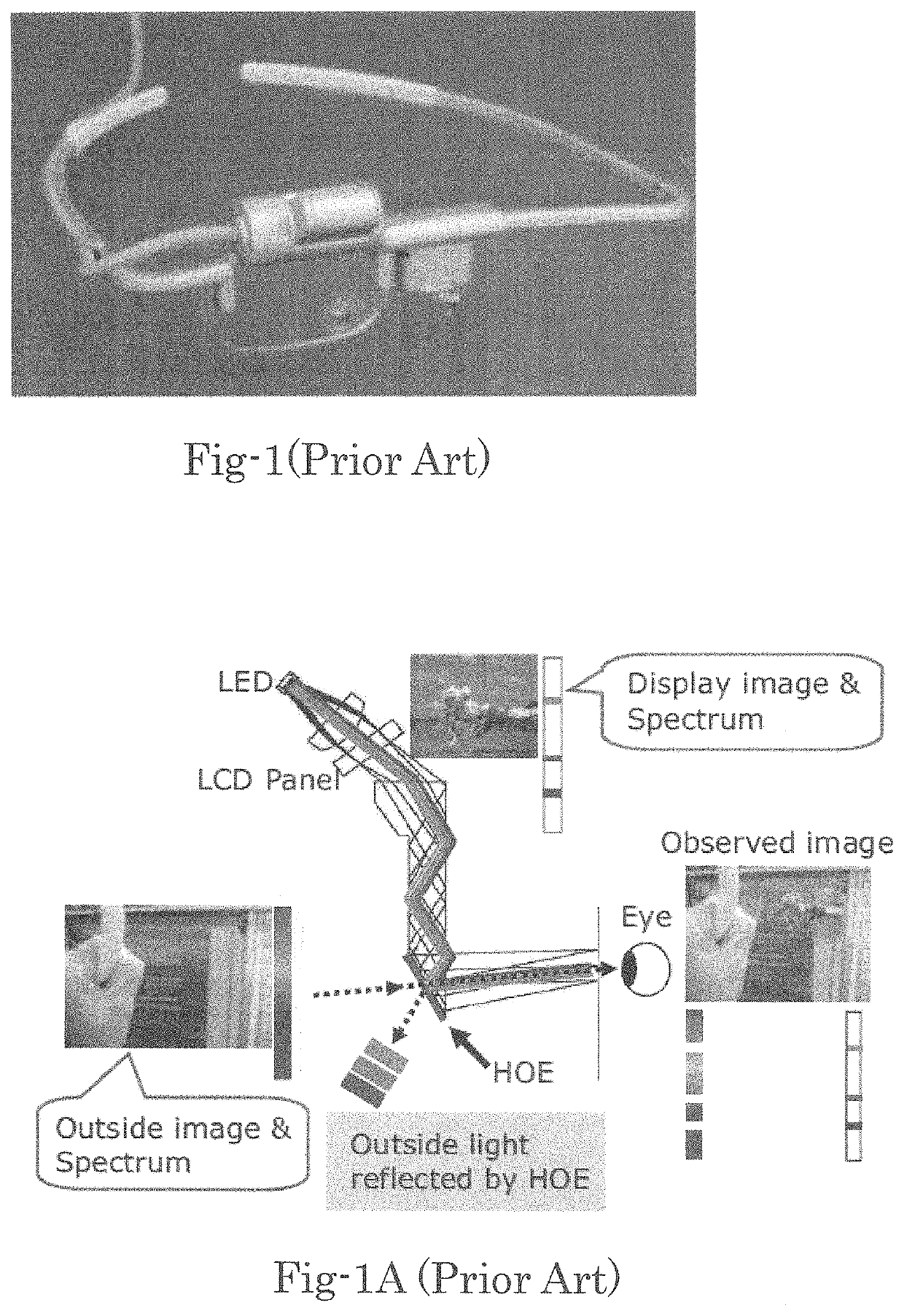
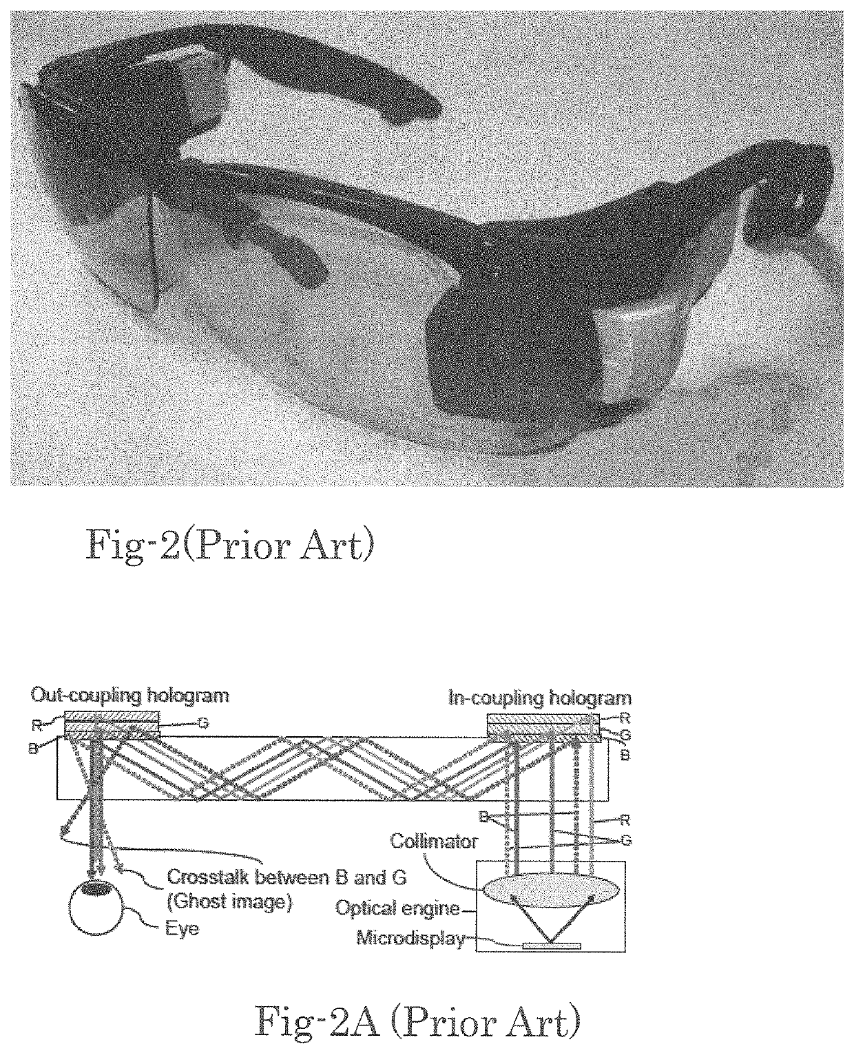
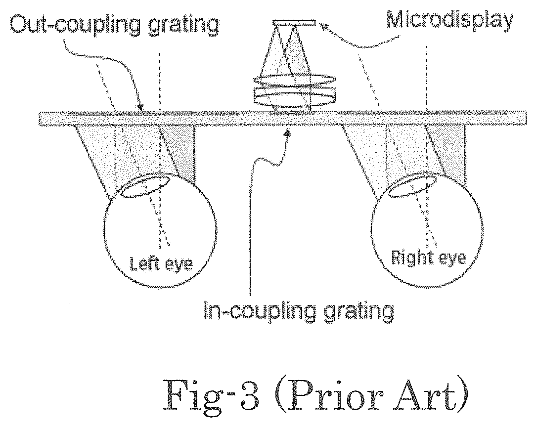
[0009]One prospect of this invention is to provide a see-through near eye display with a field of view that is nearly full size of the eyeglass. Another prospect of this invention is to provide the wearable display system with very compact optics and electronics of the system that can be embedded in the temple of eyeglass as will be further illustrated in different embodiments of this invention. Specifically, this invention discloses display device such as LCOS, LCD or DMD that is used to project an image toward a lens of eyeglass from its temple. As shown in different embodiments, this invention take advantages of the geometrical configuration of eyeglass and human eye wherein an image is projected from the temple of eyeglass to its eye-lens and reflected to a human eye. Furthermore, in order to keep the visibility of external scene, a hologram is used. Hologram can reflect only specified narrow band-width of light and the rest of light can pass through. Because of this narrow band selectivity of hologram, it will reflect the image light having the specified band-width and the image is superimposed onto the external image, so that viewer can see through the eyeglass. Different from the conventional display systems as that shown in FIG. 1 and FIG. 2, image light is projected from the temple of eyeglass directly without passing through a wave-guide. This arrangement allows much larger projection area than that of an optical projection using a waveguide. The wearable display device of this invention thus enables a viewer to perceive a larger field of view with improved resolution. Additionally, the large aberrations such as Astigmatic and Comma caused by a tilted projection of the wearable devices are compensated to achieve high resolution. These aberration problems are resolved in this invention with a hybrid optical configuration implemented with a newly developed technique by combining both geometrical optics and wave optics simultaneously in addition to the usage of free-form lens and mirror.
[0011]To increase the resolution and to minimize the distortion, another lens is added as illustrated in FIG. 20. This example incorporates three free-form lenses (2005, 2006 and 2007), a free-from mirror (2004) and a hologram (2002).
[0012]Another exemplary embodiment of this invention is illustrated in FIG. 21, wherein three free-form lenses are used to increase the field of view. This exemplary embodiment shows a wearable display device with 67 degrees of field of view without sacrificing resolution and distortion.

Problems solved by technology

Because of these advantages, there are tremendous needs for wearable displays.
However, the conventional near eye displays such as Head Mount Display, Head up Display and Eye Glass Type Display have not provided satisfied wearable display solutions to the viewers, because these conventional devices are often too heavy, too large, and too dark.
Furthermore, these conventional wearable displays often have low resolution and many of them do not provide a see-through view and are mostly expensive and can only display small size of images.
However, due to the use of a waveguide, the field of view and resolution are very limited.
Again, this type of eye glass also uses a waveguide which limits a resolution the images and the field of view.
However, such display system requires large protruded space which enlarges the form factor thus making the device too large and inconvenient as a wearable display system.
The above three types of displays are using either holographic optical element (HOE) or diffractive optical element (DOE) and all of these optical displays have fundamental difficulties of large chroma aberration, cross talk of colors, large field curvature aberration and distortion aberration.
However, due to the size of field of view and resolution these systems have limited usefulness.

Method used


Image

  • Optics of wearable display devices
  • Optics of wearable display devices
  • Optics of wearable display devices

Examples


Embodiment Construction

[0043]The detail descriptions of various embodiments below illustrate various see-through display wearable device with high resolution up to 4K (8 million pixels) and a large field of view over 60 degrees are provided in devices that have a very small form factor fitting inside the temple of eyeglass.

[0044]FIG. 7 shows an example wherein an image in air as a see-through display, i.e., a virtual image, is generated in front of the eyes of viewer. The light rays (7102) containing the images are projected from side toward an eyeglass pane (7101) and an optical element (7103) reflects the light rays toward the pupil (7105) of eye (7108) and focused onto the retina (7107). The optical element (7103) has to reflect the rays (7102) in arbitrary direction different from symmetric mirror reflection to keep the optical element thin. The optical element (7103) can be a hologram (HOE) or a diffractive optical element (DOE). Both of these can be a see-through element to generate an image (7104)....


PUM


Abstract

A see-through image display system with high resolution up to 4K, wide field of view (FOV) beyond 60 degrees and small form factor is proposed. The optics for the display incorporates optical elements including hologram, DOE, lens and mirror with free form surfaces. This display system is suitable for a wearable display.

Description

CROSS REFERENCE TO RELATED APPLICATIONS[0001]This application is a Non-Provisional Application that claims the benefits of a previously filed Provisional Application 62 / 493,082 filed on Jun. 21, 2016. This Application is also a Continuation in Part (CIP) of Patent Application PCT / US2014 / / 000153 filed on Jun. 23, 2014, which is a Non-Provisional Application of a Provisional Application 61 / 957,258 filed on Jun. 27, 2013.TECHNICAL FIELD[0002]This invention relates to a display system for projecting an image to a diffractive optical element enabling a see-through display with high resolution and wide field of view. More particularly, this invention relates to a display suitable for wearable displays with very small form factor.BACKGROUND ART[0003]Wearable displays have received broad attention in recent years after smart phones became popular and are well accepted by the market. Wearable displays provide the benefits of hands free operation as well as showing the images to the person wh...

Claims


Application Information

Patent Timeline
Patent Type & Authority Patents(United States)
IPC IPC(8): G02B27/10H04N9/79G02B27/48G03B21/20G02B17/00G02B5/20G02B27/01G02B3/04G02B5/10
CPCG02B3/04G02B5/208H04N9/7908G02B27/48G02B17/008G02B5/10G02B27/0172G03B21/204G02B2027/0116G02B2027/0178G02B2027/0123G02B2027/0174G02B2027/011G03B21/14
Inventor ISHII, FUSAOABURAKAWA, YUJITAKAHASHI, KAZUHIKOMURAKAMI, KEIICHINAKANISHI, MIKIKO
Owner ISHII FUSAO MR
Why Eureka
Try Eureka