Wireless power transmission device

a power transmission device and wireless technology, applied in the direction of transformers, inductances, transportation and packaging, etc., can solve the problems of significant location freedom and limited power transfer distance, and achieve the effect of reducing noise and reducing carrier power with respect to power transmitted

Active Publication Date: 2020-01-21
GE HYBRID TECH
View PDF16 Cites 5 Cited by
  • Summary
  • Abstract
  • Description
  • Claims
  • Application Information

AI Technical Summary

Benefits of technology

[0007]The present invention provides a wireless power transmission apparatus which efficiently reduces a carrier power with respect to power transmitted to a wireless power reception apparatus in a contactless charging system.
[0015]The fifth and sixth condensers may be configured to reduce noise due to a voltage applied to the other condensers.
[0018]The attenuating of the reflection power may include reducing the reflection power applied to the power source by first and second condensers disposed at both ends of the primary coil.
[0022]First and second grounds may be connected to both ends of the inductor, a fifth condenser may be connected between the inductor and the first ground, and a sixth condenser may be connected between the inductor and the second ground to reduce noise due to a voltage applied to the first and second condensers.
[0023]According to an embodiment of the present invention, a carrier power with respect to power transmitted to a wireless power reception apparatus in a contactless charging system can be efficiently reduced.

Problems solved by technology

The magnetic induction type of wireless power transfer technology has an advantage of high transmission efficiency, but has limitations in that the power transfer distance is limited to several millimeters and the degrees of the location freedom is significantly low due to sensitivity to matching between coils.

Method used


Image

  • Wireless power transmission device
  • Wireless power transmission device
  • Wireless power transmission device

Examples


Embodiment Construction

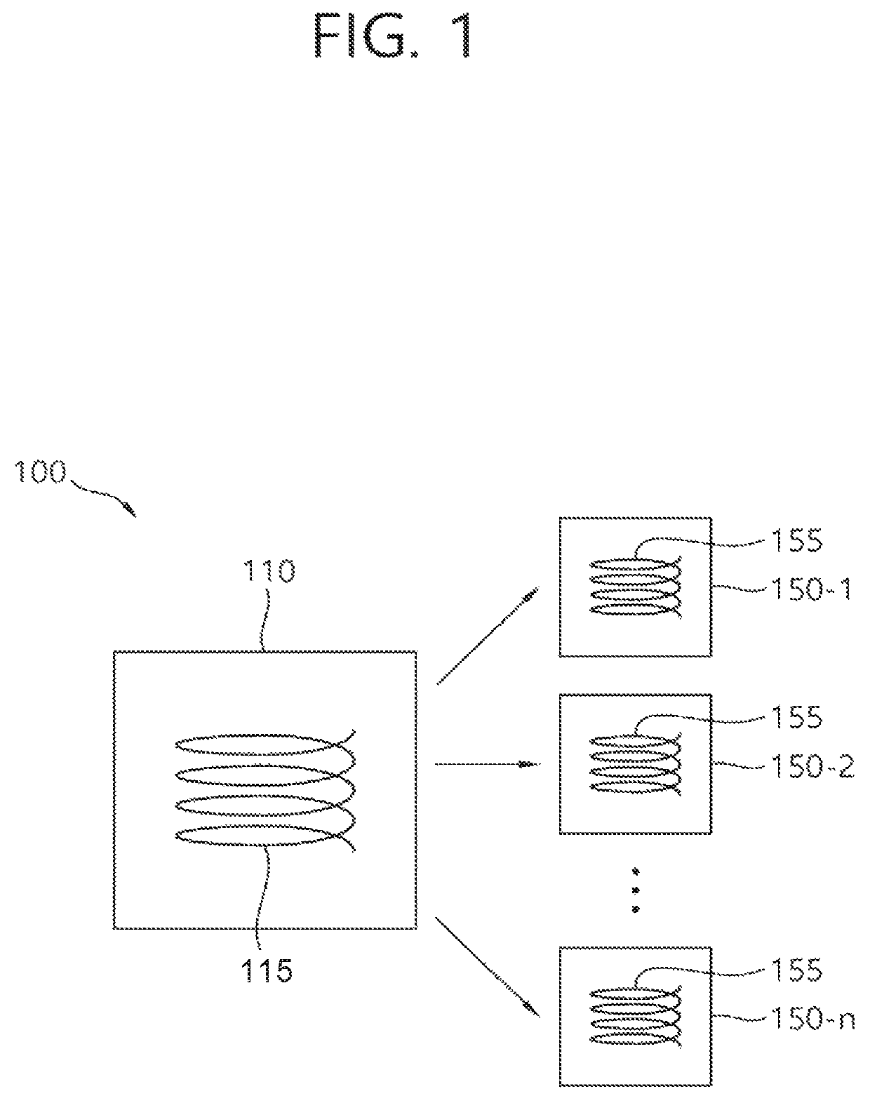
[0029]The term ‘wireless power’ below is used to mean any type of energy associated with an electric field, a magnetic field, and an electromagnetic field transmitted from a wireless power transmission apparatus to a wireless power reception apparatus without the use of physical electromagnetic conductors. The wireless power may also be referred to as a power signal or wireless energy, and may denote an oscillating magnetic flux enclosed by the primary and secondary coils. For example, power conversion in a system to wirelessly charge devices including mobile phones, cordless phones, iPods, MP3 players, headsets and the like will be described herein. In this disclosure, the basic principles of wireless power transmission include, for example, both magnetic induction coupling and magnetic resonance coupling that uses frequencies of less than 30 MHz. However, various frequencies at which license-exempt operations at relatively high radiation levels, for example, less than 135 kHz (LF)...


PUM

PropertyMeasurementUnit
frequenciesaaaaaaaaaa

Abstract

The present specification relates to a wireless power transmission device. The present specification provides a wireless power transmission device comprising: a power supply unit for supplying power to the wireless power transmission device; at least one first coil for transmitting power to a wireless power reception device; and first and second condensers configured so as to be connected respectively to different both ends of the power supply unit and the first coil.

Description

CROSS-REFERENCE TO RELATED APPLICATIONS[0001]This application is a national stage of International Application No. PCT / KR2016 / 000466, filed Jan. 15, 2016, which claims the benefit of priority to U.S. Provisional Application No. 62 / 104,094, filed Jan. 16, 2015, the disclosures of which are incorporated herein by reference.BACKGROUND OF THE INVENTIONField of the Invention[0002]The present invention relates to wireless charging and, more particularly, to a no-contact point power transmission apparatus.Related Art[0003]The wireless power transfer technology is a technology that wirelessly delivers power between a power source and an electronic device. For example, the wireless power transfer technology enables a battery of a wireless terminal to be charged by simply placing a wireless terminal such as a smart phone or a tablet on a wireless charging pad. Thus, compared to a wired charging environment using a typical wired charging connector, the mobility, convenience, and safety can be ...

Claims


Application Information

Patent Timeline
Patent Type & Authority Patents(United States)
IPC IPC(8): H01F38/14H04B5/00H02J50/12H02J7/02
CPCH02J50/40H04B5/0075H02J50/12H01F38/14H04B5/0037H04B5/0081
Inventor JUNG, CHUN KILKIM, HAK DO
Owner GE HYBRID TECH
Why Eureka
Try Eureka