Sensor system and method for monitoring a powertrain

a technology of powertrain and sensor system, which is applied in the direction of converting sensor output, structural/machine measurement, instruments, etc., can solve the problems of small longitudinal and/or torsional strain (or angular displacement) at the surface of the shaft, difficult to effectively detect torsional torque and longitudinal strain of a rotating shaft member, and difficult to measure small deformation of the drive shaft. , to achieve the effect of increasing the range in which the fiber can withstand bending, reducing

Active Publication Date: 2020-01-28
OPTICS11 BV
View PDF22 Cites 1 Cited by
  • Summary
  • Abstract
  • Description
  • Claims
  • Application Information

AI Technical Summary

Benefits of technology

[0008]Advantageously, the connection structure may cause strain and resulting deformation on the strain sensitive element to be amplified with respect to that on the drive shaft. Accordingly, strain induced deformation of the strain sensitive element at a distance remote from the shaft can be larger than the strain induced deformation e.g. directly at a surface of the shaft. For example, a torque force on the drive shaft may cause a small twisting deformation of the structure of the drive shaft. The twisting deformation e.g. at an outer surface of the drive shaft can be amplified by a rigid connection between the shaft and the strain sensitive element or sensor held at a radial distance from the drive shaft. Also other deformations, e.g. bending of the shaft may be amplified via the connection structure. By using a connection structure that is optionally separable from the drive shaft, it can also be more convenient to install and / or replace the sensors on the drive shaft.
[0019]By using an optional temperature sensor, the system may compensate for temperature offset and / or drift, e.g. temperature induced changes of the optical properties of the strain sensitive elements. Advantageously, an optical temperature sensor can be arranged along a length of the one or more optical fibres. For example, the optical temperature sensor may comprise another FBG. By tightly wrapping the fibre with optical temperature sensor around the structure of the drive shaft or connection structure (e.g. along a looped or helical path), a temperature change may cause expansion or contraction of the structure leading to a wavelength shift of the optical temperature sensor. Advantageously, the wavelength shift caused by the expansion or contraction of the shaft / connection structure may be the same direction as the wavelength shift caused by the direct effect of the temperature on the sensor. For example, the sensitivity of the optical temperature sensor can be enhanced by a factor of two, or more.

Problems solved by technology

When a drive shaft is subjected to mechanical forces such as torque and thrust, these can result in small longitudinal and / or torsional strains (or angular displacement) at the surface of the shaft.
However, effectively detecting torsional torque and longitudinal strain of a rotating shaft member can be difficult to implement.
This is a particular problem in the shipping industry where such measuring and monitoring systems typically operate in a harsh or hostile environment.
However, it can be difficult to measure small deformations of the drive shaft.
However, the known system may be complex to install and prone to installation errors that would lead to erroneous measurements.
Furthermore, the known system may have difficulty distinguishing different types of deformation, e.g. separating torsion, bend, and axial deformations.
Advantageously, the connection structure may cause strain and resulting deformation on the strain sensitive element to be amplified with respect to that on the drive shaft.
For example, a torque force on the drive shaft may cause a small twisting deformation of the structure of the drive shaft.

Method used


Image

  • Sensor system and method for monitoring a powertrain
  • Sensor system and method for monitoring a powertrain
  • Sensor system and method for monitoring a powertrain

Examples


first embodiment

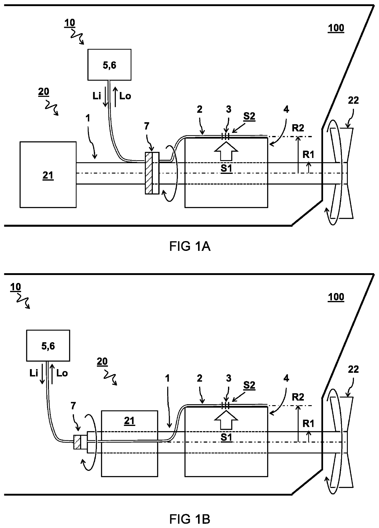
[0038]FIG. 1A schematically illustrates a sensor system 10 for monitoring a powertrain 20 having a drive shaft 1.

second embodiment

[0039]FIG. 1B schematically illustrates a sensor system 10 for monitoring a powertrain 20 having a drive shaft 1.

[0040]In one embodiment, the sensor system 10 comprises an optical fibre 2 comprising a strain sensitive element 3 configured to change its optical properties as a function of strain S2 on the sensor. For example, the strain sensitive element or optical strain sensor may comprise an FBG, fibre laser, multicore fibre, and / or birefringent FBG. In one embodiment, at least a part of the optical fibre 2 comprising the strain sensitive element 3 is pre-stressed in absence of strain on the drive shaft 1. In one embodiment, a light source 5 is connected to the optical fibre 2 and configured to emit an input light signal Li to the optical fibre 2 for optical interaction with the strain sensitive element 3. In one embodiment, a light detector 6 is configured to receive an output light signal Lo from the optical fibre 2 resulting from the optical interaction of the input light signa...

third embodiment

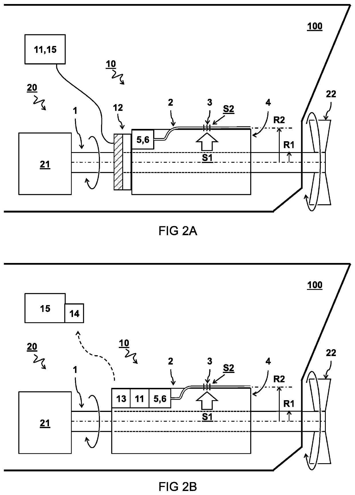
[0049]FIG. 2A schematically illustrates a sensor system 10 wherein the system is comprised in a rotating structure, in this case the housing of the connection structure 4 attached to the drive shaft 1. In the embodiment, the system comprise an electrical slip ring 12 for passing electrical signals between a stationary frame and a rotating frame of the light source 5 and / or light detector 6. The slip rings can have many form factors, including ones with boreholes so that rotary components pass through them. The electrical signals may include power to the light source 5 and / or light detector 6 from the power source 11. Alternatively, or in addition, the electrical signals may include control and / or sensor signals, from and to the controller 15.


PUM

PropertyMeasurementUnit
angleaaaaaaaaaa
thermal conductivityaaaaaaaaaa

Abstract

A sensor system (10) and method for monitoring a powertrain (20) having a drive shaft (1). The sensor system (10) comprises an optical fibre (2) with a strain sensitive element (3). According to one aspect, a connection structure (4) is configured to hold at least a part of the optical fibre (2) with the strain sensitive element (3) at a radial distance (R2-R1) remote from the drive shaft (1) for amplifying the strain (S2) on the strain sensitive element (3) with respect to the strain (51) on the drive shaft (1). According to a further aspect, at least three respective lengths of one or more optical fibres follow parallel, e.g. helical, paths with respect to each other to distinguish different strain forces.

Description

CROSS-REFERENCE TO RELATED APPLICATIONS[0001]This application is a national stage application of International Application No. PCT / NL2015 / 050319, which was filed on May 8, 2015, of which is incorporated by reference in its entirety.TECHNICAL FIELD AND BACKGROUND[0002]The present disclosure relates to a sensor system and method for monitoring a powertrain, in particular a powertrain comprising a drive shaft.[0003]A powertrain or propulsion system is typically used to transfer mechanical energy into movement, for example movement of a vehicle, aircraft, or ship. A powertrain is formed by the main components that generate power and deliver it e.g. to the road surface, water, or air. This may include e.g. an engine, drive shaft, and final drive. A drive shaft or propulsion shaft is a mechanical component for transmitting torque and rotation between components of a powertrain, e.g. between the engine and final drive, or components there between. The final drive may e.g. include wheels, p...

Claims


Application Information

Patent Timeline
Patent Type & Authority Patents(United States)
IPC IPC(8): G01L1/24G01M11/08G01B11/16G01L3/12G01L3/14G01L5/13G01D5/353
CPCG01L1/246G01L3/12G01M11/085G01L5/133G01B11/18G01D5/35316G01L3/14G01L5/166G01L5/12G01M5/0025G01M5/0091
Inventor SINGER, JOHANNES MARIAKARABACAK, DEVREZ MEHMETHEFFERNAN, BILL
Owner OPTICS11 BV
Why Eureka
Try Eureka