Magnetoresistive wheatstone measuring bridge and angle sensor having at least two such measuring bridges

a technology of magnetic resistor and angle sensor, which is applied in the direction of magnetic measurement, measurement device, instruments, etc., can solve the problems of high manufacturing complexity, inability to achieve optimal evaluation, and inability to achieve the homogeneity of resistance behaviour in particular of tmr- or gmr-based resistor arrangements, etc., to achieve high sensor accuracy

Active Publication Date: 2020-02-11
SENSITEC
View PDF13 Cites 7 Cited by
  • Summary
  • Abstract
  • Description
  • Claims
  • Application Information

AI Technical Summary

Benefits of technology

[0026]This invention therefore describes a method for reducing the harmonics and achieving optimum resistance values. In contrast to the prior art, harmonics are not suppressed in the individual resistor arrangements, but rather are suppressed via functional interaction of different magnetic preferred directions of all the bridge resistor arrangements throughout the measuring bridge. In this way, the signal is improved and the resolution of the sensor is improved, wherein a smaller number of sub-resistors may be used. In the case of an angle sensor, angular accuracy may be increased thereby. The filtering of harmonics of a magnetoresistive resistance bridge is made possible by specifying the preferred directions Rres1 and Rres2 of the diagonally opposing resistor arrangements of the measuring bridge, wherein the overall sensitivity direction Rres results from vector addition of preferred sub-directions Rres1 and Rres 2 of diagonal resistor arrangements R2 and R3 or R1 and R4. The number and orientations of the magnetoresistive sub-resistors of each resistor arrangement in the two bridge branches are determined by the harmonic filtering, the overall preferred direction being the resultant thereof. No bridge resistor arrangement has a preferred direction which corresponds with the overall preferred orientation of the measuring bridge, and the resistor arrangements of the two half-bridges have different individual preferred directions and preferred directions.
[0041]In one advantageous further development of the angle sensor, sub-resistors R1X and R3X of the resistor arrangements R1, R3 of the first bridge branch R1-R3 may be arranged spatially adjacently on a chip substrate, and sub-resistors R2X, R4X of the resistor arrangements R2, R4 of the second bridge branch R2-R4 may be arranged spatially adjacently on the chip substrate. The first and second bridge branches R1-R3 and R2-R4 of each sensor bridge may be arranged diagonally relative to one another on the chip substrate. Thus, the resistor groups of the two bridge branches are situated diagonally relative to one another and adjacent to bridge branches of a measuring bridge advantageously rotated by 90°. Thus, the resistor arrangements of a sine and a cosine bridge may be arranged compactly and obliquely relative to one another in a 4-quadrant grid. This results in a space-saving, low-offset design for an angle sensor. Due to the close spatial proximity of the resistor arrangements of the measuring bridge, manufacturing-related scatter may be mutually compensated and high sensor accuracy achieved.

Problems solved by technology

With regard to manufacture, this can only be achieved in most cases with great difficulty or not at all, such that moreover the desired trigonometric curves of the measurement signals and optimal evaluation cannot be achieved.
A disadvantage of the prior art is that filtering of harmonics by means of magnetoresistive resistor arrangements can only be achieved with high manufacturing complexity.
Furthermore, homogeneity of the resistance behaviour in particular of TMR- or GMR-based resistor arrangements can be achieved only with difficulty, since the resistance values may be widely scattered during production.

Method used


Image

  • Magnetoresistive wheatstone measuring bridge and angle sensor having at least two such measuring bridges
  • Magnetoresistive wheatstone measuring bridge and angle sensor having at least two such measuring bridges
  • Magnetoresistive wheatstone measuring bridge and angle sensor having at least two such measuring bridges

Examples


seventh embodiment

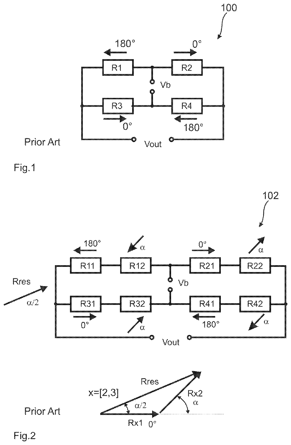
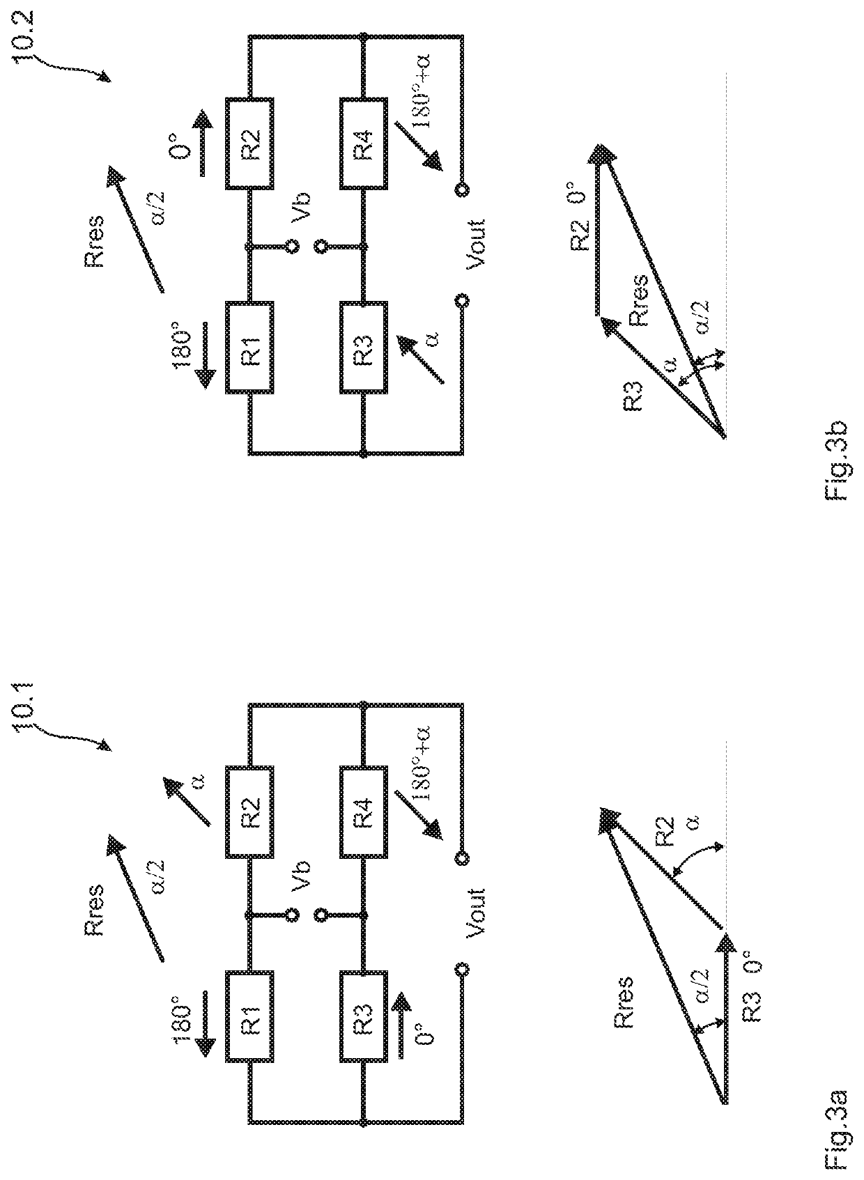
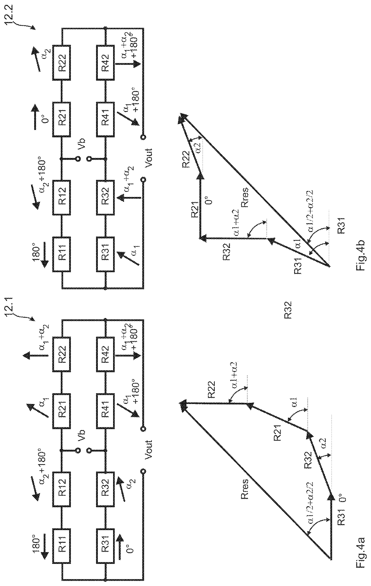
[0107]10 First embodiment of a Wheatstone bridge[0108]12 Second embodiment of a Wheatstone bridge[0109]14 Third embodiment of a Wheatstone bridge[0110]16 Fourth embodiment of a Wheatstone bridge[0111]18 Fifth embodiment of a Wheatstone bridge[0112]20 Sixth embodiment of a Wheatstone bridge[0113]22 Seventh embodiment of a Wheatstone bridge[0114]24 Eighth embodiment of a Wheatstone bridge[0115]30 Angle sensor[0116]32 Chip substrate[0117]34 Contact pad[0118]36 Conductor track[0119]38 Magnetoresistive bridge resistor[0120]40 Sine bridge[0121]42 Cosine bridge[0122]50 Trimming resistor[0123]52 Top electrode[0124]54 Tunnel resistor / tunnel element[0125]56 Bottom electrode[0126]58 Insulation layer[0127]60 Electrode interruption[0128]100 Prior art Wheatstone bridge[0129]102 Prior art Wheatstone bridge


PUM


Abstract

A magnetoresistive Wheatstone bridge includes two bridge branches connected in parallel between a supply potential Vb, wherein two series-connected resistor arrangements R1 and R3 or R2 and R4 are arranged in each bridge branch with an interposed measuring potential Vout. The resistor arrangements of the two bridge branches are situated diagonally opposite one another and at least two magnetoresistive resistor arrangements have a magnetically sensitive preferred direction. The preferred directions of diagonally opposing resistor arrangements of the bridge branches R1 and R4 or R2 and R3 differ by an angle other than 0° or 180°. An angle sensor includes at least two of the Wheatstone bridges offset by a predefined angle for determining an angular orientation of a magnetic field by a sine bridge and a cosine bridge. The measuring bridge reduces harmonics and optimizes resistance values, improving the accuracy of a phase-angle sensor signal and the sensor resolution.

Description

[0001]This application is a National Stage Application of International Patent Application No. PCT / EP2015 / 077571, filed Nov. 24, 2015, which claims benefit of German Patent Application No. 10 2014 117 160.8, filed Nov. 24, 2014 and which applications are incorporated herein by reference. To the extent appropriate, a claim of priority is made to each of the above disclosed applications.[0002]The invention relates to a magnetoresistive Wheatstone bridge and a magnetoresistive angle sensor for measuring the angular orientation of a magnetic field, which comprises at least one Wheatstone bridge, preferably two or more Wheatstone bridges offset by a predefined angle according to the teaching of claim 1.[0003]To this end, the two parallel-connected bridge branches of the Wheatstone bridge, which are also known as half-bridges, each comprise two series-connected magnetoresistive resistor arrangements R1 and R3 or R2 and R4. The resistor arrangements R1, R4 and R2, R3 of the two bridge bran...

Claims


Application Information

Patent Timeline
Patent Type & Authority Patents(United States)
IPC IPC(8): G01D5/16G01R33/04G01R33/00G01R33/09
CPCG01R33/09G01D5/16G01R33/0023G01R33/0005G01R33/04
Inventor PAUL, JOHANNESALAVI, GOLZARYIN, TSUNG-I
Owner SENSITEC
Why Eureka
Try Eureka