Deformation—measuring torque meter

a torque meter and torque technology, applied in the field of torque meter, can solve the problems of inability to guarantee the accuracy of hydraulic torque meter, the inability to use the torque meter, etc., and achieve the effect of reliable torque meter and small maintenan

Active Publication Date: 2020-02-11
SAFRAN HELICOPTER ENGINES
View PDF18 Cites 0 Cited by
  • Summary
  • Abstract
  • Description
  • Claims
  • Application Information

AI Technical Summary

Benefits of technology

[0016]A torque meter according to the invention therefore allows for the measurement of the torque of a transmission element of a transmission chain, for example a transmission shaft, without the use of a reference or power shaft or of hydraulic elements. A movable part moves in translation depending on the torque to be measured; this movable part causes a bearing surface to become deformed. The deformation of the bearing surface is therefore representative of the torque, and the measurement of this deformation can be used to determine the torque. The torque meter therefore occupies little space compared to a rotary torque meter and occupies an amount of space that is substantially less than or equal to a hydraulic torque meter, without requiring a hydraulic circuit, and thus without requiring associated sealing. The absence of any hydraulic circuit also eases maintenance.
[0037]Within the scope of using the torque meter in a turboshaft engine, the temperature variations in the torque meter can be high. The torque measurement must therefore take into account these temperature variations, in this case by reducing the effects of these variations.

Problems solved by technology

These hydraulic torque meters have the drawbacks of being sensitive to friction due to the use of sealing and bearing elements, to leaks caused by the ageing of the sealing elements, to the variation in oil viscosity, and to the temperature, etc.
Therefore, the accuracy of hydraulic torque meters is not guaranteed and regular maintenance thereof is required.
Moreover, a negative torque cannot be measured using such torque meters.
However, the accuracy of the torque measurement taken by rotary torque meters depends on the length of the shaft, which thus requires rotary torque meters to be particularly bulky in order to produce an accurate measurement.
Moreover, the rotating shaft not subject to the torque, and used as a reference, represents an additional cost and weight for the system.

Method used


Image

  • Deformation—measuring torque meter
  • Deformation—measuring torque meter

Examples


second embodiment

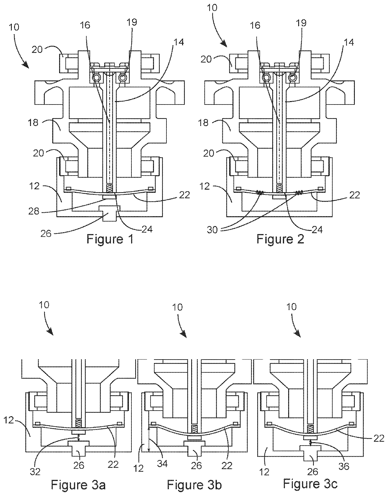
[0046]FIG. 2 is a diagrammatic sectional view of a torque meter

[0047]FIG. 3a is a diagrammatic sectional view of a part of a torque meter according to one embodiment of the invention, measuring a torque C, at a temperature of 0° C.,

[0048]FIG. 3b is a diagrammatic sectional view of a part of a torque meter according to one embodiment of the invention, measuring a torque C, at a temperature of 150° C. and comprising a temperature-sensitive bearing surface and a casing that is not sensitive to temperature variations,

[0049]FIG. 3c is a diagrammatic sectional view of a part of a torque meter according to one embodiment of the invention, measuring a torque C, at a temperature of 150° C. and comprising a casing and a bearing surface that are sensitive to temperature variations,

third embodiment

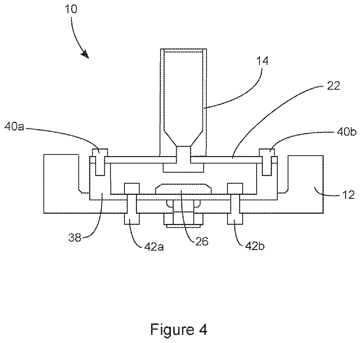
[0050]FIG. 4 is a diagrammatic sectional view of a torque meter according to the invention.

6. DETAILED DESCRIPTION OF ONE EMBODIMENT OF THE INVENTION

[0051]The following embodiments are examples. Although the description refers to one or more embodiments, this does not necessarily mean that each reference relates to the same embodiment, or that the characteristics apply only to a single embodiment. Simple characteristics of different embodiments can also be combined in order to provide other embodiments. For illustration and clarity purposes, the scales and proportions are not strictly respected in the figures.

[0052]FIGS. 1 and 2 diagrammatically illustrate a sectional view of a torque meter 10 according to a first and second embodiment of the invention. The torque meter 10 comprises a casing 12, in which can move a part 14 capable of moving in translation. The translational displacement of the movable part 14 takes place in a longitudinal direction, in this case parallel to an axis ...

first embodiment

[0057] shown in FIG. 1, the means for measuring the deformation of the bearing surface 22 comprise a proximity sensor 26, also called a proximeter, allowing the distance between itself and the bearing surface 22 to be measured. Depending on the torque to be measured, this distance varies as a result of the displacement of the bearing surface 22 in the longitudinal direction. The comparison between the distance measured when applying a torque and the distance measured when no torque is applied can be used to determine the displacement of the bearing surface 22. The torque meter 10 can further comprise a fastening 28 for fixedly connecting the movable part 14 to the bearing surface 22. In this case, the proximity sensor 26 can measure the distance between itself and the fastening 28, instead of the bearing surface 22, which does not affect the torque measurement, which is based on the difference between the distances measured with or without torque.

[0058]The proximity sensor 26 is adv...


PUM

PropertyMeasurementUnit
temperatureaaaaaaaaaa
distanceaaaaaaaaaa

Abstract

A torque meter includes a casing and a part is configured to move in the casing in translation in a longitudinal direction under the effect of an axial thrust representative of the torque to be measured. The torque meter further includes a bearing surface connected to the casing via at least one of the ends thereof. The bearing surface extends at least partially in a plane that is substantially perpendicular to the longitudinal direction. One longitudinal end of the movable part is configured to be brought into contact with the bearing surface so that a longitudinal displacement of the movable part leads to a deformation of the bearing surface. The torque meter also has a device configured to measure the deformation of the bearing surface.

Description

1. TECHNICAL FIELD OF THE INVENTION[0001]The invention relates to a torque meter. In particular, the invention relates to a torque meter for measuring a torque of a transmission element of a turboshaft engine of an aircraft.2. TECHNOLOGICAL BACKGROUND[0002]Torque meters are torque-measuring devices that exist in multiple formats depending on the field of application, the equipment for which the torque must be measured and the degree of accuracy required. In the aeronautical field, hydraulic torque meters are commonly used. These torque meters operate, for example, by means of an intermediate helical-toothed gear, for which the torque applied results in an axial thrust proportionate to the torque to be measured. This axial thrust is applied to a piston connected to the intermediate gear. Another embodiment commonly encountered involves measuring the axial thrust of a ring gear of an epicyclic gear train, which is also proportionate to the torque to be measured. In more general terms,...

Claims


Application Information

Patent Timeline
Patent Type & Authority Patents(United States)
IPC IPC(8): G01L3/14
CPCG01L3/1457G01L3/1428F02K9/96
Inventor FULLERINGER, BENJAMINBUENO, ARMANDCAZAUX, YANNICK
Owner SAFRAN HELICOPTER ENGINES
Why Eureka
Try Eureka