Device and method for correction of geometrical differences of the surfaces of parts to be assembled at the assembly interface

a technology of geometric differences and devices, applied in the field of parts assembly, can solve problems such as inability to guarantee the deformation of parts, discrepancies in the geometry of nominal surfaces, and distortion of shapes and dimensions

Active Publication Date: 2020-02-18
AIRBUS
View PDF5 Cites 0 Cited by
  • Summary
  • Abstract
  • Description
  • Claims
  • Application Information

AI Technical Summary

Benefits of technology

[0017]An objective of the present invention is to propose a device and a method for correcting geometrical differences of the surfaces of two parts to be assembled at the interface of the assembly in which the introduction of unwanted stresses into the parts to be assembled is limited if not prevented.
[0019]Another objective of the present invention is to avoid the necessity for supplementary manipulation of the parts to be assembled.
[0025]Thanks to these features of the device, correction of the geometrical discrepancies of the surfaces to be assembled is achieved without degrading the mechanical strength of the parts to be assembled, in that only added material is deposited on the assembly surface of at least one of the parts to be assembled. This material does not affect the integrity of the parts to be assembled, whatever their shape or the material from which they are made. The mechanical strength of the parts is therefore controlled.
[0043]This step makes it possible to simulate assembly in a manner that is more representative of reality, in the sense that the shapes and positions of the simulated assembly surfaces relative to one another after bringing them into contact in this way is representative of the position of the assembly surfaces of the parts relative to one another following their assembly.

Problems solved by technology

The imperfections of the methods of fabricating parts lead to dispersion in terms of the shapes and dimensions of the geometrical envelope of the parts produced and therefore discrepancies between the geometry of their nominal surfaces, i.e. the geometry of their intended theoretical surfaces, and the geometry of their real surfaces obtained after fabrication.
Moreover, in the case of rigid parts, it is not always possible to guarantee the deformation of the part to ensure the intimate contact of the assembled parts.
However, the use of mastics of this kind is irksome and is not always possible, depending on the forces that have to be transmitted in the joint and the assembly elements used.
Moreover, mastics having appropriate structural properties are dense and this can result in an increase in the weight of the assembled structure, which is all the more problematic in that it is not controlled.
The operations of fabrication of a part or of correction of the geometry of its nominal surface are relatively complex to implement if that part is a thin part, for example a metal sheet, in that the removal of material can significantly reduce the mechanical strength of the part.
Moreover, the correction operations may be impossible to carry out without affecting the integrity of the part if the thickness of the part becomes less than a minimum necessary for the transmission of the designed forces in the part.
Moreover, these operations necessitate supplementary manipulations of the parts to be assembled and therefore a significant loss of time on the production or assembly line.

Method used


Image

  • Device and method for correction of geometrical differences of the surfaces of parts to be assembled at the assembly interface
  • Device and method for correction of geometrical differences of the surfaces of parts to be assembled at the assembly interface

Examples


Embodiment Construction

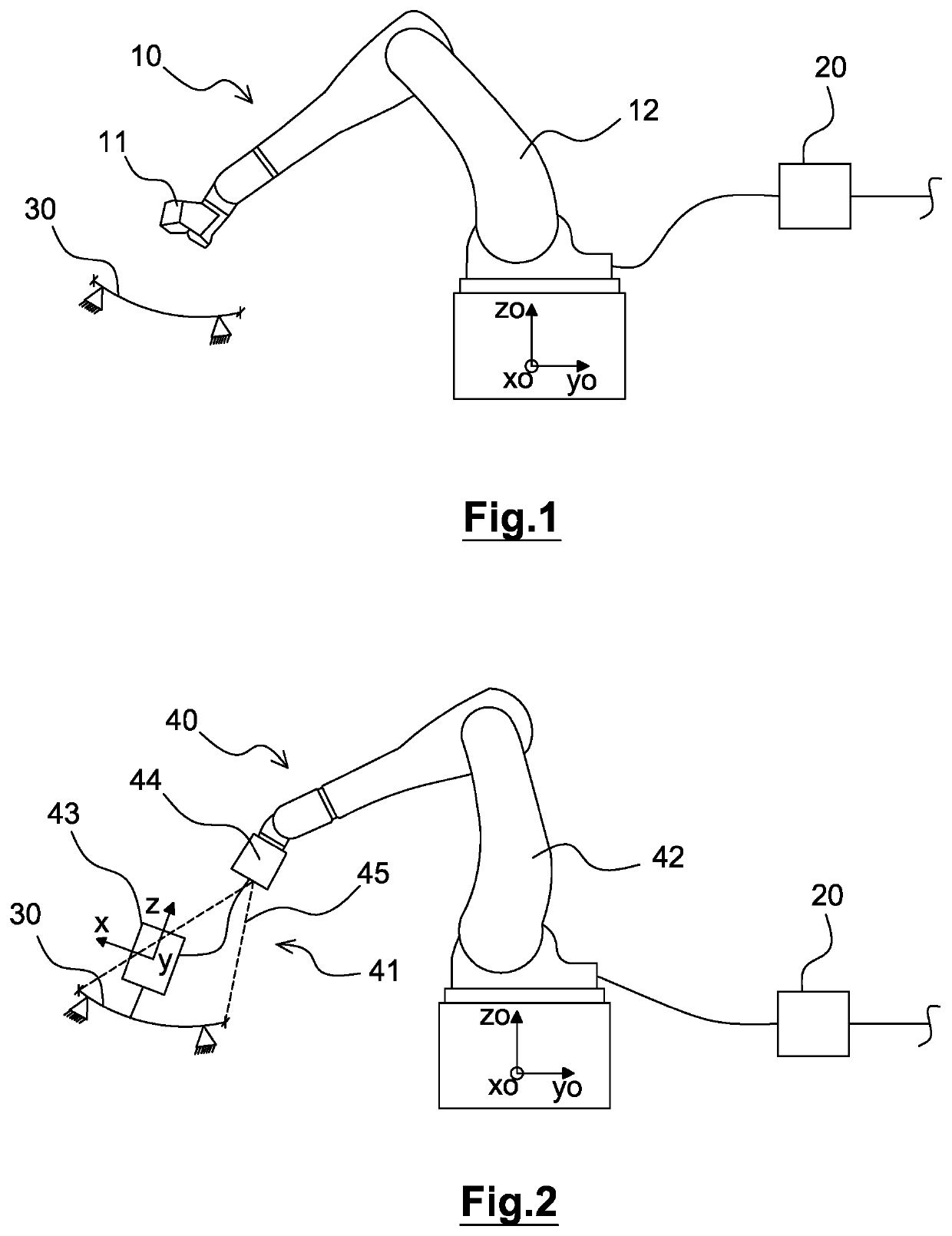
[0051]The present invention relates to a device for correction of geometrical differences of the surfaces of two parts that are brought into contact during assembly of said two parts. These surfaces that are brought into contact, termed “assembly surfaces” in the present description, are intended to be disposed facing one another when assembling the parts.

[0052]The description and the drawings refer to the surfaces of the parts in contact. Although only said surfaces are represented, it must be understood that the parts can be any shape and that the invention can be applied, for example, to thin parts such as cladding panels or to profiled elements or to thick parts of any shape, with no particular limitations as to dimensions and materials other than may be imposed by the means employed.

[0053]The correction device comprises acquisition means 10 by measurement of the geometry of the surfaces of at least two parts to be assembled in an area of each of the parts the surface of which m...


PUM

PropertyMeasurementUnit
thicknessaaaaaaaaaa
forcesaaaaaaaaaa
structureaaaaaaaaaa

Abstract

A device to correct geometrical differences of surfaces of parts to be assembled at the interface of the assembly. A measurer to acquire data by measuring the geometry of the assembly surfaces of two parts to be assembled to each other with their respective assembly surfaces facing. A simulator configured to simulate the assembly of the parts and to determine from the acquired data at each measured point of a sampling of the interface a thickness of the void resulting from the geometrical discrepancies between the assembly surfaces. An additive fabricator to receive from the simulator data representative of the thicknesses of the voids resulting from the geometrical discrepancies between the assembly surfaces. The additive fabricator configured to deposit material on the assembly surface of at least one of the parts to at least partly fill the void resulting from the geometrical discrepancies between the assembly surfaces.

Description

RELATED APPLICATIONS[0001]This application claims priority from French Patent Application No. 15 63462 filed Dec. 30, 2015, which is incorporated herein by reference in its entirety.FIELD OF THE INVENTION[0002]The present invention lies in the field of the assembly of parts intended to produce a mechanical structure and more particularly concerns a device and a method for correcting geometrical differences of the surfaces of parts to be assembled at the interface of the assembly.BACKGROUND OF THE INVENTION[0003]The imperfections of the methods of fabricating parts lead to dispersion in terms of the shapes and dimensions of the geometrical envelope of the parts produced and therefore discrepancies between the geometry of their nominal surfaces, i.e. the geometry of their intended theoretical surfaces, and the geometry of their real surfaces obtained after fabrication.[0004]Complex mechanical structures are often produced by assembling a plurality of parts held together by mechanical ...

Claims


Application Information

Patent Timeline
Patent Type & Authority Patents(United States)
IPC IPC(8): B29C70/74B33Y50/02B33Y10/00B33Y30/00B29C64/00B29C70/84B29K105/20
CPCB29C70/84B29C70/745B33Y30/00B33Y10/00B33Y50/02B29K2105/20B23P19/10G05B19/4099G05B19/41805G05B2219/35062G05B2219/37205G05B2219/40613B64F5/10Y02P80/40B29C64/393Y02P90/02
Inventor DOUILLY, MARCRABATE, PATRICEFALGARONE, HUGO
Owner AIRBUS
Why Eureka
Try Eureka