Projection lens and projector

a projection lens and projector technology, applied in the field of projection lenses and projectors, can solve the problems of increasing achieve the effects of avoiding the increase of the radial size of the projection lens, reducing the size of the projector, and being more resistant to external impa

Active Publication Date: 2020-02-18
SEIKO EPSON CORP
View PDF3 Cites 0 Cited by
  • Summary
  • Abstract
  • Description
  • Claims
  • Application Information

AI Technical Summary

Benefits of technology

[0006]An advantage of some aspects of the invention is to provide a projection lens that is resistant to external impact and prevents an increase in the radial size when fixed to a projector via a flange. Another advantage of some aspects of the invention is to provide a projector that projects an image via the projection lens.
[0008]In the projection lens according to the aspect of the invention, a barrel that holds the one or more lenses includes the lens group holding tube, the cam tube, and the guide tube in the direction from the side facing the inner circumference of the barrel toward the outer circumference thereof. The barrel (guide tube) is directly provided with the flange. Therefore, when the projection lens is fixed to a frame or any other component of the projector via the flange, and impact externally acts on the projection lens, the barrel can receive the impact. The projection lens can therefore be more resistant to external impact than in a case where a member including the flange is provided separately from the barrel and the projection lens so configured that the member including the flange supports the barrel in the form of a cantilever is fixed to the frame or any other component of the projector. Further, since the barrel (guide tube) is directly provided with the flange, no member including the flange needs to be disposed on the side facing the outer circumference of the barrel. An increase in the radial size of the projection lens can therefore be avoided. Moreover, since no member including the flange needs to be provided separately from the barrel, the number of parts of the projection lens can be reduced.
[0009]In the aspect of the invention, it is desirable that the flange is provided on the guide tube and located in an intermediate position in the optical axis direction. The flange can therefore be readily provided in a position close to the center of gravity of the projection lens. When the position of the flange is close to the center of gravity of the projection lens, the projection lens, when it is fixed to the frame or any other component of the projector via the flange, is supported by the frame in a well-balanced manner.
[0010]In the aspect of the invention, it is desirable that the guide tube includes the guide groove in an inner circumferential surface thereof, and that the guide groove includes a penetration section that extends over part of the guide groove in the optical axis direction and passes through the guide groove in a radial direction. Adjusting the relative angular positions of the cam tube and the guide tube around the optical axis therefore allows the cam hole of the cam tube to communicate with the penetration section of the guide tube. Therefore, in the state in which the cam hole and the penetration section communicate with each other, the guide pin can be attached to the lens group holding tube, which is located on the side facing the inner circumference of the cam tube, from the side facing the outer circumference of the guide tube via the penetration section and the cam hole. Further, it is easy to achieve the state in which the guide pin attached to the lens group holding tube passes through the cam hole in the cam tube and is inserted into the guide groove in the guide tube.
[0011]In the aspect of the invention, it is desirable that the guide tube is a resin molded part, that the flange has a fixing hole that passes therethrough in the optical axis direction, that the flange and the penetration section are provided in different positions in the optical axis direction, and that the fixing hole and the penetration section are provided indifferent angular positions around the optical axis. It is therefore easy to fill a die with a resin to mold the guide tube. That is, to provide the flange of the guide tube with the fixing hole, which passes through the flange in the optical axis direction, the die needs to include a pin for forming the fixing hole, and a movable die for the fixing hole that is movable in the axial direction (axial direction of guide tube) needs to be provided. Further, to provide the guide tube with the penetration section, which passes through the guide tube in the radial direction, a protrusion for forming the penetration section needs to be provided, and a movable die for the penetration section that is movable in the radial direction needs to be provided. In this situation, providing the flange and the penetration section in different positions in the optical axis direction and providing the fixing hole and the penetration section in different angular positions around the optical axis can prevent interference between the movable die of the fixing hole and the movable die for the penetration section when the two dies are moved. The guide tube can therefore be readily molded.
[0013]According to the aspect of the invention, the barrel of the projection lens formed of the lens group holding tube, the cam tube, and the guide tube is directly provided with the flange of the projection lens. Therefore, when the projection lens is fixed to the frame of the projector via the flange, and impact externally acts on the projection lens, the barrel can receive the impact. The projection lens can therefore be more resistant to external impact. Further, since the barrel (guide tube) is directly provided with the flange, no member including the flange needs to be disposed on the side facing the outer circumference of the barrel. An increase in the radial size of the projection lens can therefore be avoided. The space where the projection lens is disposed in the projector can therefore be reduced. The size of the projector can therefore be readily reduced. Moreover, since no member including the flange needs to be provided separately from the barrel, the number of parts of the projection lens can be reduced. The number of parts of the projector can therefore be reduced, whereby the cost required to manufacture the projector can be reduced.

Problems solved by technology

Further, in the projection lens described in JP-A-2012-220915, the attachment tubular member including the flange includes the tubular portion located on the side facing the outer circumference of the lens barrel, resulting in a problem of an increase in the radial size of the projection lens.

Method used


Image

  • Projection lens and projector
  • Projection lens and projector
  • Projection lens and projector

Examples


Embodiment Construction

[0020]A projection lens and a projector according to an embodiment of the invention will be described below with reference to the drawings.

Projector

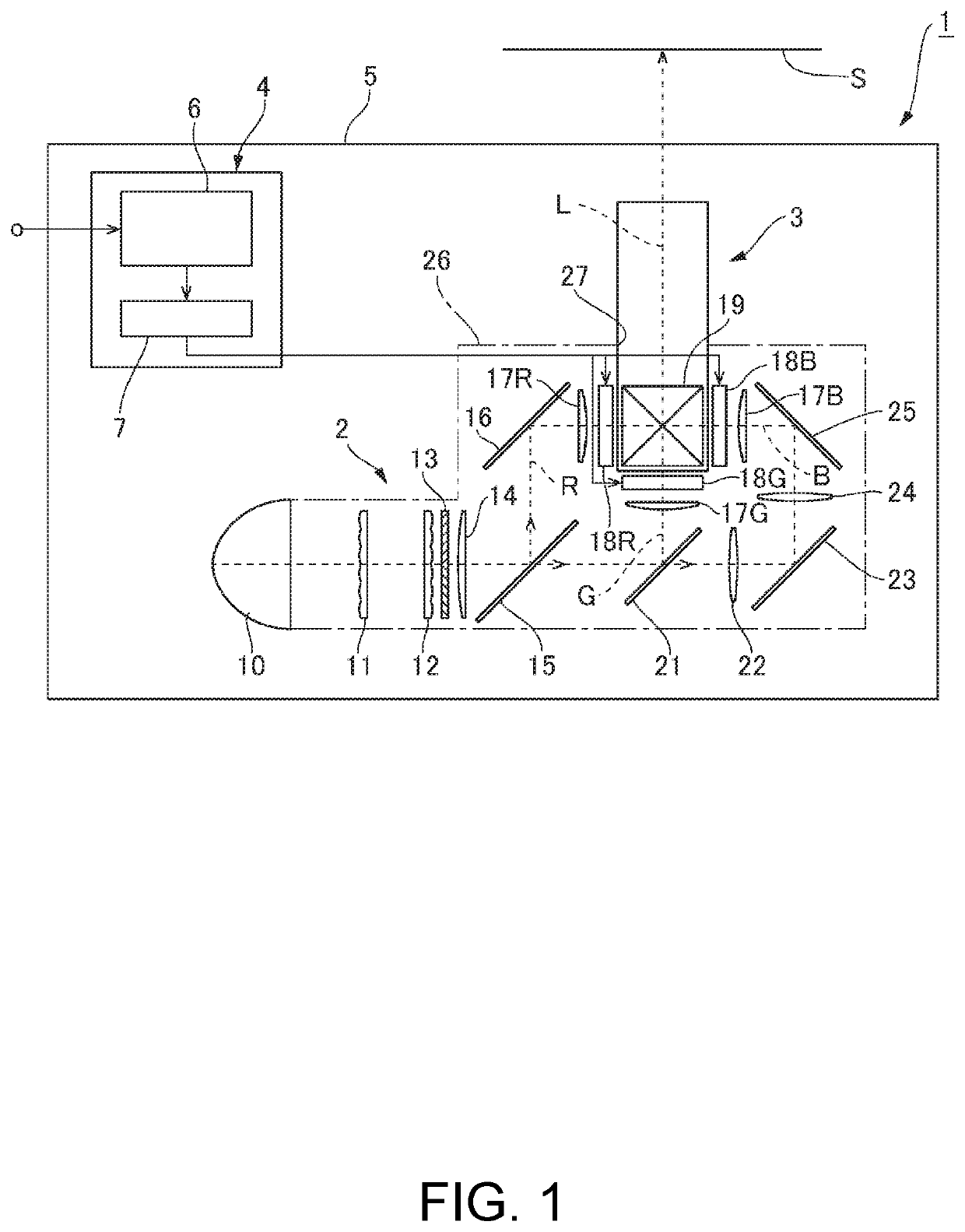
[0021]FIG. 1 is a schematic configuration diagram of a projector including a projection lens according to the embodiment of the invention. A projector 1 includes an image light generation system 2, which generates image light to be projected on a screen S, a projection lens 3, which enlarges and projects the image light, and a controller 4, which controls the action of the image light generation system 2, as shown in FIG. 1. The projection lens 3, the image light generation system 2, and the controller 4 are accommodated in an enclosure 5.

Image Light Generation System and Controller

[0022]The image light generation system 2 includes a light source 10, a first optical integration lens 11, a second optical integration lens 12, a polarization conversion element 13, and a superimposing lens 14. The light source 10 is formed, for example, of a...


PUM


Abstract

A projection lens includes a lens group holding tube including lenses on the side facing the inner circumference of the lens group holding tube, a cam tube that supports the lens group holding tube movably in the optical axis direction, and a guide tube that supports the cam tube rotatably around the optical axis. The lens group holding tube includes a guide pin that protrudes outward from the lens group holding tube. The cam tube has a cam hole which inclines with respect to the optical axis direction along the circumferential direction and through which the guide pin passes. The guide tube includes a guide groove which extends in the optical axis direction and into which the guide pin is so inserted as to pass through the inner circumference of the guide groove and a flange that protrudes outward.

Description

BACKGROUND[0001]1. Technical Field[0002]The present invention relates to a projection lens including a lens group holding tube that moves in the optical axis direction, and to a projector that projects an image displayed on an image display device via a projection lens.[0003]2. Related Art[0004]JP-A-2012-220915 describes a projection lens incorporated in a projector. The projection lens described in JP-A-2012-220915 includes a lens barrel and an attachment tubular member for fixing the lens barrel to a fixing portion of the projector. The lens barrel includes a plurality of lenses and a barrel that holds the lenses in such a way that the outer circumferences thereof are held. The attachment tubular member includes an annular plate portion, a tubular portion that extends forward in the projection direction (toward enlargement side) from the outer-circumferential-side end portion of the plate portion, and a flange that protrudes outward from the tubular portion. The plate portion is f...

Claims


Application Information

Patent Timeline
Patent Type & Authority Patents(United States)
IPC IPC(8): G02B7/02G02B9/64G03B21/14
CPCG03B21/142G02B9/64G02B7/021G02B7/025H04N9/317G02B7/04G02B7/022G02B13/16
Inventor TAKEHANA, NAOTO
Owner SEIKO EPSON CORP
Why Eureka
Try Eureka