Failure detection and correction control system of machine tool using chronological control data

a control system and machine tool technology, applied in the field of control system of machine tools, can solve problems such as detection of failures on machined surfaces

Active Publication Date: 2020-02-18
FANUC LTD
View PDF46 Cites 0 Cited by
  • Summary
  • Abstract
  • Description
  • Claims
  • Application Information

AI Technical Summary

Benefits of technology

[0009]The present invention has an object to provide the control system of a machine tool which reduces, based on failure information detected from spatial machined surface measurement data after the machining of a work, the occurrence of a failure on the machined surface of the work.
[0020]According to the present invention, it is possible to provide the control system of a machine tool which reduces, based on failure information detected from image data on the machined surface of a work, the occurrence of a failure on the machined surface of the work.

Problems solved by technology

In other words, the failure on the machined surface is detected from spatial machined surface measurement data after the machining of the work.

Method used


Image

  • Failure detection and correction control system of machine tool using chronological control data
  • Failure detection and correction control system of machine tool using chronological control data
  • Failure detection and correction control system of machine tool using chronological control data

Examples


first embodiment

Numerical Control System of Machine Tool

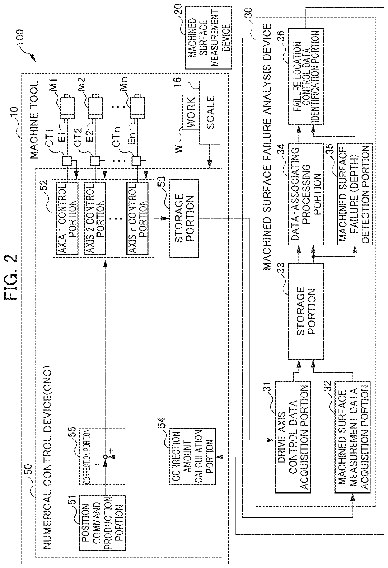
[0039]Net, the numerical control system of a machine tool according to a first embodiment of the present invention will be described. FIG. 2 is a diagram showing the configuration of the numerical control system in the machine tool according to the first embodiment of the present invention. The numerical control system 100 of the machine tool shown in FIG. 2 includes the machine tool 10 described above, a machined surface measurement device 20 and a machined surface failure analysis device 30.

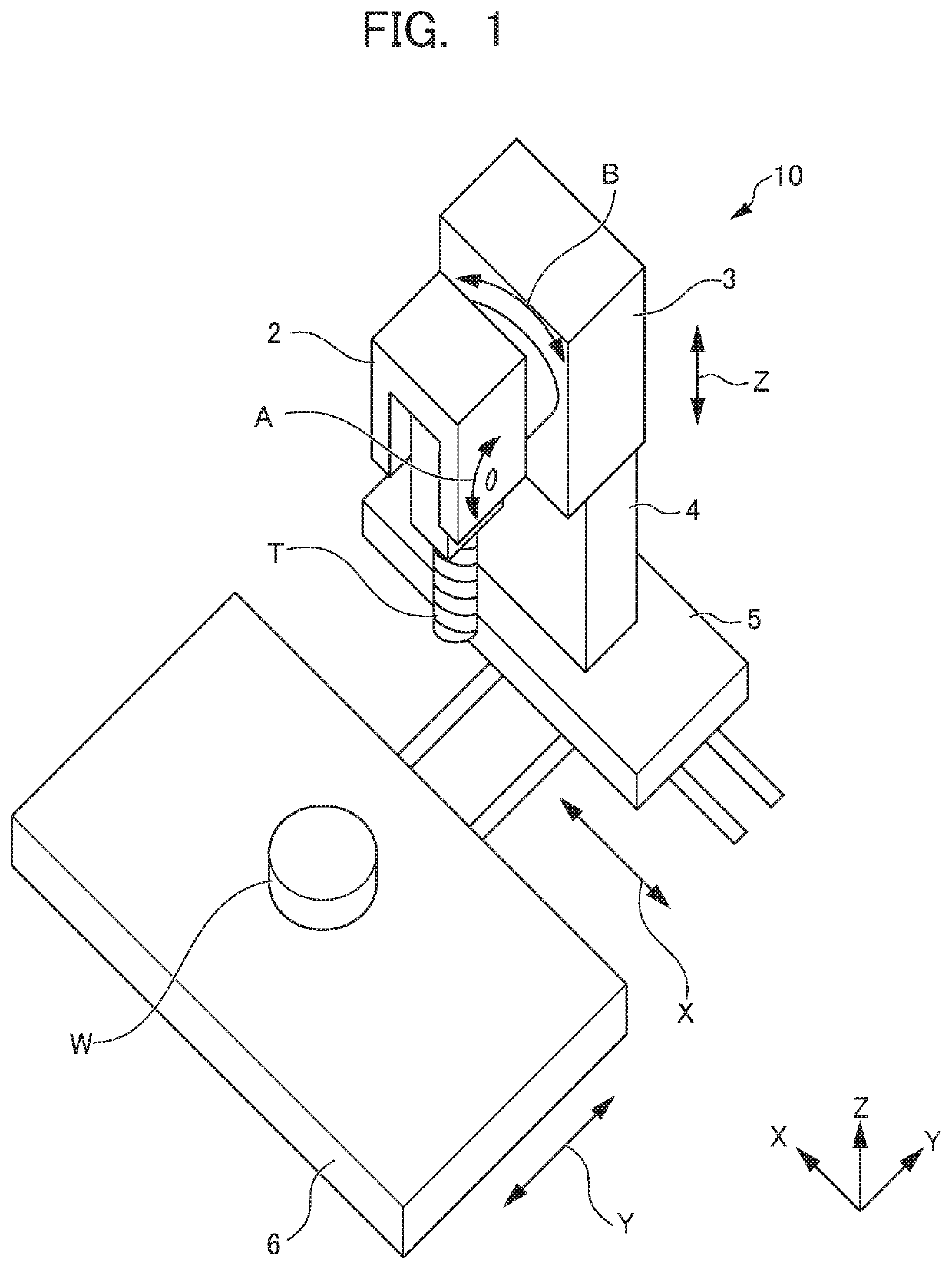
[0040]Although in the machine tool 10 described above, the five drive axes (the X axis, the Y axis, the Z axis, the A axis and the B axis) are illustrated, the machine tool 10 of the present embodiment includes n drive axes. The machine tool 10 includes n servomotors M1, M2, . . . and Mn corresponding to the drive device described above, encoders (position / speed detectors) E1, E2, . . . and En which are respectively provided in the servomotors thereof, cu...

second embodiment

Numerical Control System of Machine Tool

[0076]In the first embodiment, the position command value is corrected according to the failure depth of the machined surface of the work W. In a second embodiment, at least any one of the speed, the acceleration and the jerk in movement command data generated by acceleration / deceleration processing is changed according to the failure depth of the machined surface of the work W.

[0077]FIG. 8 is a diagram showing the configuration of a numerical control system in a machine tool according to the second embodiment of the present invention. A numerical control system 100A of the second embodiment shown in FIG. 8 differs from the numerical control system 100 of the first embodiment shown in FIG. 2 described above in that instead of the numerical control device 50, a numerical control device 50A is included.

[0078]The numerical control device 50A includes, instead of the correction amount calculation portion 54 and the correction portion 55 in the num...


PUM


Abstract

A control system of a machine tool includes an analysis device, the analysis device includes acquisition portions which acquire chronological speed control data when a work is machined and which acquire spatial machined surface measurement data after the machining of the work, a data-associating processing portion which associates the speed control data and the machined surface measurement data with each other, a machined surface failure detection portion which detects a failure depth of a failure location on the machined surface of the work and an identification portion which identifies the control data of the failure location corresponding to the machined surface measurement data of the failure location so as to identify a failure depth corresponding to the control data of the failure location and the numerical control device corrects the control data based on the control data of the failure location and the corresponding failure depth.

Description

[0001]This application is based on and claims the benefit of priority from Japanese Patent Application No. 2017-081395, filed on 17 Apr. 2017, the content of which is incorporated herein by reference.BACKGROUND OF THE INVENTIONField of the Invention[0002]The present invention relates to the control system of a machine tool which machines a work.Related Art[0003]A machine tool machines a work while moving at least one of the work (the item to be machined) and a tool along predetermined drive axes. In other words, the machine tool machines the work while varying a relative position of the work and the tool.[0004]When the work is machined with the machine tool described above, a stripe pattern (failure) may occur on the machined surface of the work due to any cause such as vibrations. In other words, streaks or stripes may occur at predetermined intervals.[0005]Hence, for example, Patent Documents 1 and 2 disclose technologies in which based on the movement path of the tip of a tool wh...

Claims


Application Information

Patent Timeline
Patent Type & Authority Patents(United States)
IPC IPC(8): G05B19/404B23Q1/48B23Q1/62B23Q1/54
CPCB23Q1/4857G05B19/404B23Q1/623B23Q1/5406G05B2219/33315G05B19/4142G05B2219/34013G05B2219/37206G05B2219/37347G05B2219/49176
Inventor IKAI, SATOSHIHASHIMOTO, SHOUTAROU
Owner FANUC LTD
Why Eureka
Try Eureka