Method for artifact reduction using monoenergetic data in computed tomography

a computed tomography and monoenergetic data technology, applied in the field of computed tomography (ct) imaging systems, can solve the problems of reducing the sensitivity of the detector, affecting the detection accuracy, and affecting the detection accuracy, and achieve the effect of low contrast and high contras

Active Publication Date: 2020-02-25
PHOTO DIAGNOSTIC SYST INC
View PDF84 Cites 3 Cited by
  • Summary
  • Abstract
  • Description
  • Claims
  • Application Information

AI Technical Summary

Benefits of technology

An object imaged with a low-energy monochromatic X-ray source demonstrates a high degree of contrast between radiologically opaque and transparent objects, while an object imaged with a high-energy monochromatic X-ray source shows relatively low contrast between materials. Likewise, high-energy X-rays are less likely to be impeded by metal and the images generated from high-energy X-ray data suffer less from metal artifacts.
The present invention combines high-energy data and low-energy data in such a way so as to maximize the benefits of both. In regions of data where metal has not impacted measurements, low-energy data is preferred because of its high contrast characteristics, whereas in regions impacted by metal, high-energy data is preferred because of its inherent resistance to artifacts.
This method represents a simple, and computationally inexpensive means for reducing metal artifacts.

Problems solved by technology

As a result, efforts have been made to eliminate these artifacts, however, all of the approaches developed to date suffer from various disadvantages, e.g., computational overhead, image accuracy, etc.
Unfortunately, both the material characteristics (mu) and the length of the path through the object may vary with orientation.
While an X-ray detector is, ideally, capable of detecting smaller and smaller quantities of X-rays, detector “noise” and photon quantization place practical physical limits on detector sensitivity.
More extreme beam hardening effects can cause image artifacts more like the saturation artifacts described above.
However, this approach is expensive and hence impractical for most applications.
However, this approach does not work well where the object comprises metal.
More particularly, a simple beam hardening correction which assumes that all mu values are close to that of water will not accurately correct for beam hardening where there is metal present in the scan field and will lead to streaks within the image.
Other approaches for correcting for beam hardening may perform better in the presence of metal, but these often involve multiple reconstructions (backprojections) and / or data modelling (forward projections), and can be computationally expensive.
Hence, synthetic monoenergetic images generated using two different polyenergetic X-ray sources still do not perfectly correct for the beam hardening effects of metals.
These interpolation methods fail when the adjacent detector channels, used for the interpolation, have data values which are different from the adjacent tissue, e.g., where a staple is near bone and soft tissue.
In addition, these schemes generally rely on simple linear or polynomial interpolations which are not guaranteed to generate values which are consistent with a physical object.
In general, this class of metal artifact corrections reduces some artifacts, but often generates new artifacts.
The use of priors in security applications poses a greater challenge because of the wider range of materials encountered.
This class of metal artifact corrections is still limited in its efficacy and can be computationally expensive since this class of metal artifact corrections involves a forward projection of a complete image.
This approach is one of the most effective means for reducing metal artifacts, but is often complex and computationally expensive.

Method used


Image

  • Method for artifact reduction using monoenergetic data in computed tomography
  • Method for artifact reduction using monoenergetic data in computed tomography
  • Method for artifact reduction using monoenergetic data in computed tomography

Examples


Embodiment Construction

Metal Artifact Correction Using Monoenergetic Data

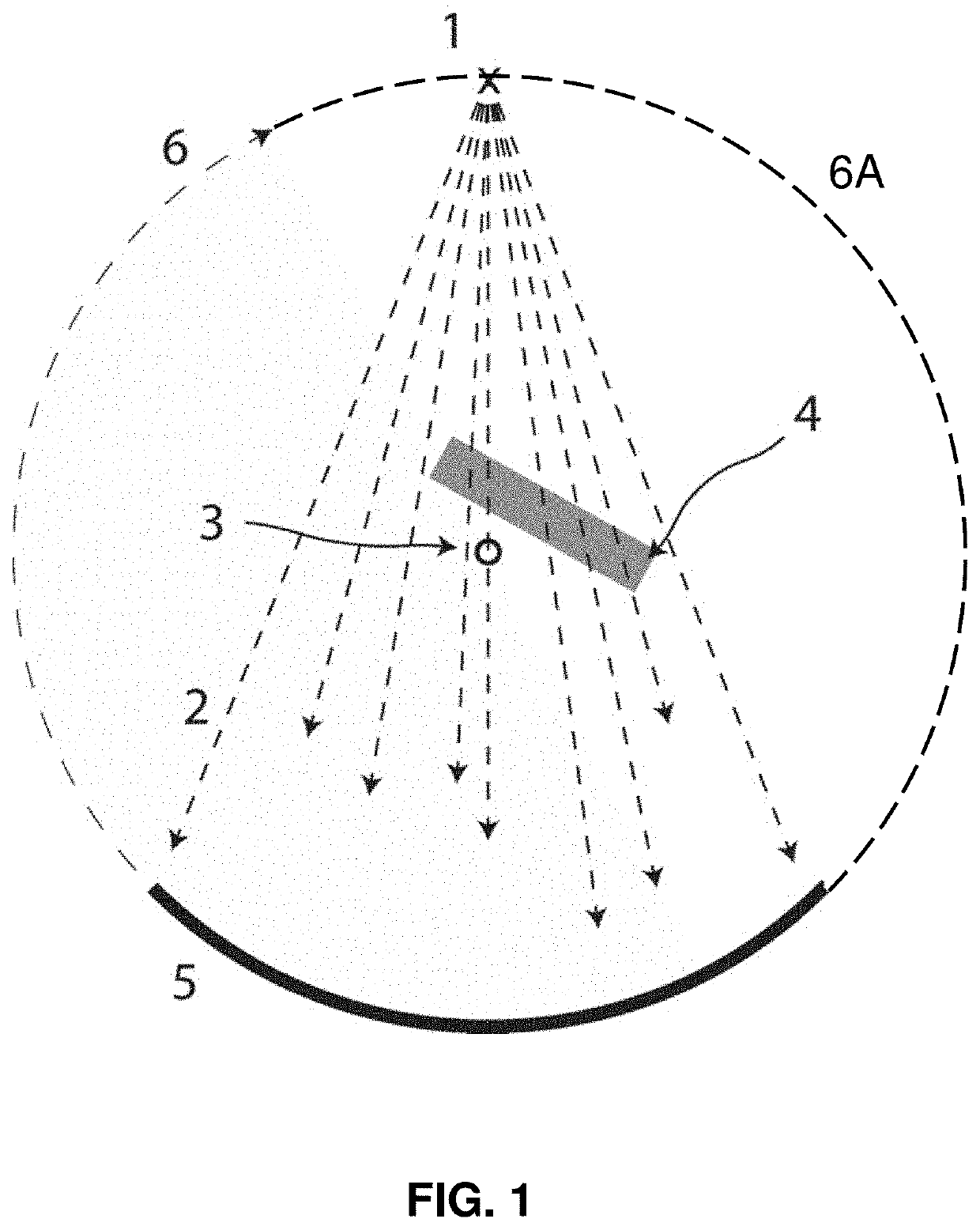
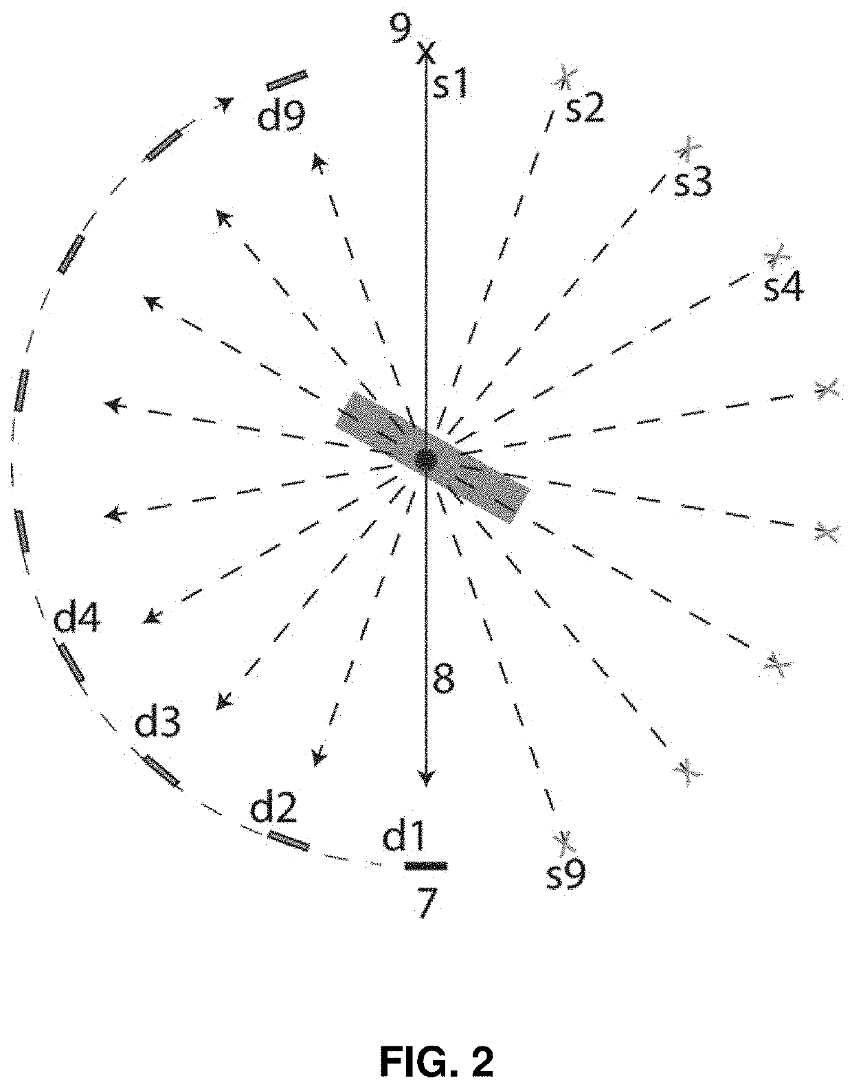
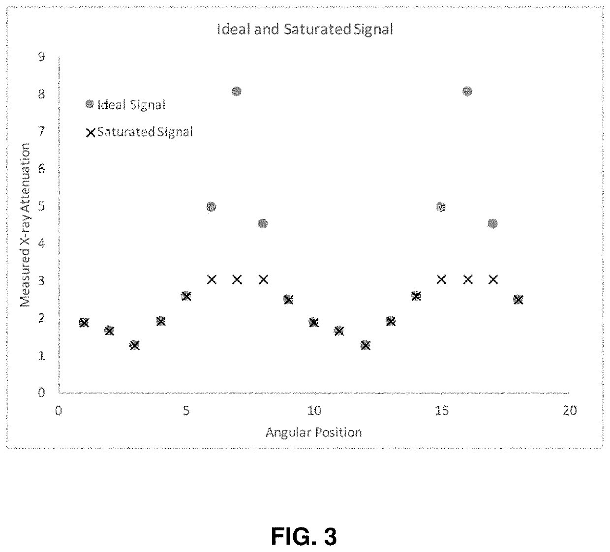
In the preferred embodiment of the present invention, several monoenergetic data sets (either approximation-derived, experimentally-measured or synthetically-derived) are used together to minimize artifacts and maximize image quality. More particularly, an object imaged with a low-energy monochromatic X-ray source demonstrates a high degree of contrast between radiologically opaque and transparent objects, while an object imaged with a high-energy monochromatic X-ray source shows relatively low contrast between materials. This is anecdotally explained by the fact that high-energy X-rays tend to simply pass through all materials, whereas low-energy X-rays are more likely to interact with the material via absorption or scattering. Likewise, high-energy X-rays are less likely to be impeded by metal and the images generated from high-energy X-ray data suffer less from metal artifacts.

The fundamental idea is to combine the high-energy dat...


PUM


Abstract

A method for artifact correction in computed tomography, the method including: (1) acquiring a plurality of data sets associated with at least one low X-ray energy, and at least one high X-ray energy; (2) generating a plurality of preliminary images from the plurality of data sets; (3) identifying sources of an artifact source image; (4) forward projecting the artifact source image to produce artifact source data; (5) selecting and combining the plurality of data sets acquired in order to produce a new subset of data associated with the artifact, whereby to produce artifact reduced data; (6) generating a repaired data set to keep data sets associated with the low X-ray energy in artifact-free data and to introduce data sets associated with the high X-ray energy in regions impacted by an artifact; and (7) generating a final reduced artifact image from the repaired data set.

Description

FIELD OF THE INVENTIONThis invention relates to imaging systems in general, and more particularly to computed tomography (CT) imaging systems.BACKGROUND OF THE INVENTIONComputed tomography uses X-ray projections from multiple vantage points to construct a three dimensional (3D) data set. This process results in the generation of a “CT” image. Each point in the 3D data set describes the X-ray attenuating properties of a corresponding point in an object in space. CT scanners are used in medicine, material diagnostics, and airport security.Metals are highly attenuating to X-rays and, because of this, they produce artifacts in reconstructed images. As a result, efforts have been made to eliminate these artifacts, however, all of the approaches developed to date suffer from various disadvantages, e.g., computational overhead, image accuracy, etc.A. ContextComputed tomography devices have a source of X-rays which are sent through an object of interest to a set of detectors. Each detector ...

Claims


Application Information

Patent Timeline
Patent Type & Authority Patents(United States)
IPC IPC(8): G06T11/00
CPCG06T11/008G06T2211/432G06T2207/10081G06T11/005G06T2211/408G06T2211/448
Inventor KEELER, MATTHEW LEN
Owner PHOTO DIAGNOSTIC SYST INC
Why Eureka
Try Eureka