

Rotating electric machine
a technology of rotating electric machines and rotating parts, which is applied in the direction of mechanical energy handling, magnetic circuit rotating parts, shape/form/construction, etc., can solve the problems of not being able to reduce the loss caused, and the part of the discharged lubricating oil cannot reach the coil end portions, so as to reduce the loss, reduce the loss, and effectively cool the coil end portions
- Summary
- Abstract
- Description
- Claims
- Application Information
AI Technical Summary
Benefits of technology
Problems solved by technology
Method used
Image

Examples
second embodiment
A rotating electric machine 1B according to a second embodiment has almost the same structure as the rotating electric machine 1A according to the first embodiment. Accordingly, the differences therebetween will be mainly described hereinafter.
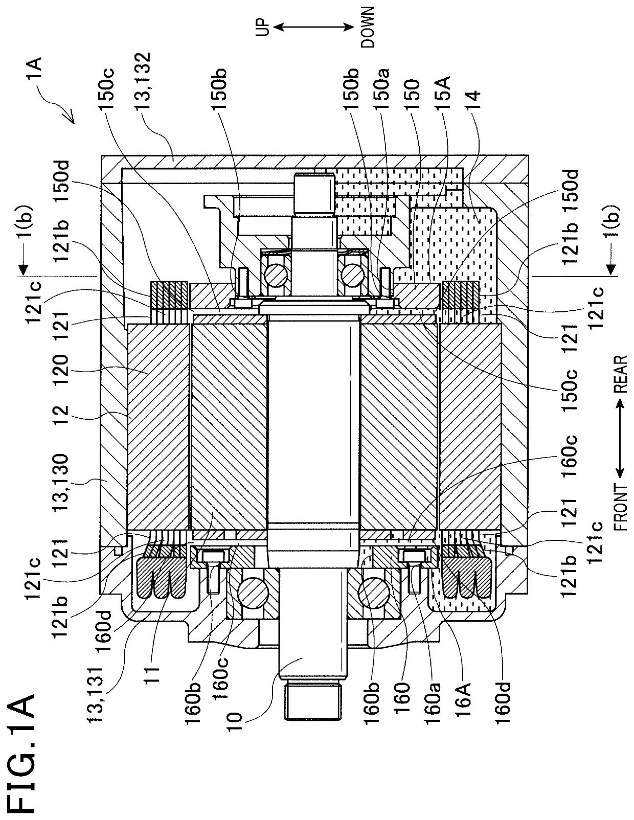
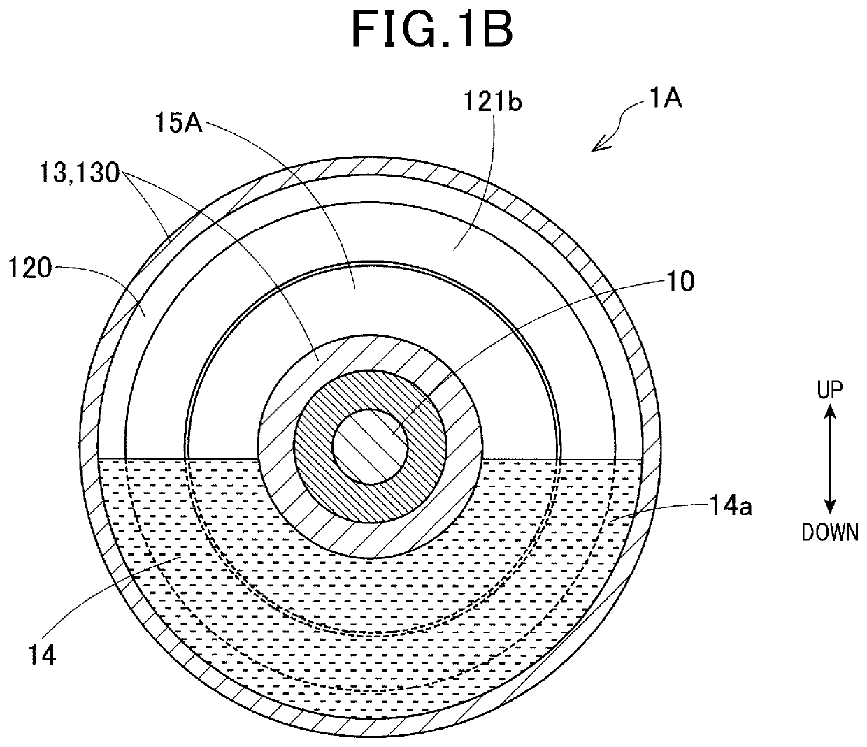
In the first embodiment, the rotating electric machine 1A includes the flow direction regulating member 15A that is arranged on the rear side of the rotor 11 and fixed to the center housing 130 (see FIG. 1A).
In comparison, in the present embodiment, as shown in FIG. 12, the rotating electric machine 1B includes, instead of the flow direction regulating member 15A, a flow direction regulating member 15B that is arranged on the rear side of the rotor 11 and fixed to the stator 12.
As shown in FIGS. 13-15, the flow direction regulating member 15B includes a main body 150 and a plurality (e.g., three) of fixing portions 151.
The main body 150 has a substantially discoid shape. The main body 150 has a planar surface facing the rear end face of the ro...
third embodiment
A rotating electric machine 1C according to a third embodiment has almost the same structure as the rotating electric machine 1A according to the first embodiment. Accordingly, the differences therebetween will be mainly described hereinafter.
In the first embodiment, the rotating electric machine 1A includes the flow direction regulating member 15A that is arranged on the rear side of the rotor 11 and has neither protrusion nor recess formed in its surface facing the rotor 11 (see FIGS. 1A and 3-5).
In comparison, in the present embodiment, as shown in FIGS. 16-19, the rotating electric machine 1C includes, instead of the flow direction regulating member 15A, a flow direction regulating member 15C that is arranged on the rear side of the rotor 11 and has protrusions 150e and recesses 150f formed in its surface facing the rotor 11.
Specifically, the flow direction regulating member 15C includes a main body 150 as shown in FIGS. 17-19. The main body 150 is made, for example, of resin an...
fourth embodiment
A rotating electric machine 1D according to a fourth embodiment has almost the same structure as the rotating electric machine 1C according to the third embodiment. Accordingly, the differences therebetween will be mainly described hereinafter.
In the third embodiment, the rotating electric machine 1C includes the flow direction regulating member 15C that is arranged on the rear side of the rotor 11 (see FIGS. 16-20).
In comparison, in the present embodiment, as shown in FIGS. 21-24, the rotating electric machine 1D includes, instead of the flow direction regulating member 15C, a flow direction regulating member 15D that is arranged on the rear side of the rotor 11 and different in shape from the flow direction regulating member 15C.
Specifically, the flow direction regulating member 15D includes a main body 150 as shown in FIGS. 22-24. The main body 150 has a plurality of first protrusions 150e, a plurality of first recesses 150f, a second protrusion 150g and a second recess 150h, all...
PUM
 Abstract
Description
Claims
Application Information