Systems for dehumidifying air and methods of assembling the same

a technology of air dehumidifier and air chamber, which is applied in the field of dehumidification, can solve the problems of increasing the cost and complexity affecting the operation and/or operation, and affecting the efficiency of the gas detection system, so as to facilitate heat transfer

Active Publication Date: 2020-03-03
GE INFRASTRUCTURE TECH INT LLC
View PDF16 Cites 0 Cited by
  • Summary
  • Abstract
  • Description
  • Claims
  • Application Information

AI Technical Summary

Benefits of technology

[0003]In one aspect, a dehumidifier assembly is provided. The dehumidifier assembly includes an extraction chamber coupled in flow communication with each of a sample air inlet, a sample air outlet, and a sample drip opening. The extraction chamber is configured to receive a sample air flow therethrough at substantially atmospheric pressure from the sample air inlet to the sample air outlet. The dehumidifier assembly also includes a conduit positioned within the extraction chamber. The conduit is coupled in flow communication with an environmental air inlet and an environmental air outlet, and is sealed with respect to the extraction chamber. The dehumidifier assembly further includes a circulator coupled to the environmental air outlet. The circulator is operable to create a negative pressure in the conduit, such that an environmental air flow is drawn through the environmental air inlet into the conduit. The conduit is configured to facilitate heat transfer from the sample air flow to the environmental air flow.

Problems solved by technology

Such relatively low temperatures may cause moisture within the air to form into ice under air sampling flow conditions, which may disrupt the operation and / or damage the components of the gas detection system, requiring an unscheduled shutdown of the gas turbine to remove the ice and / or repair the detection system.
Dehumidifiers may be used to reduce a potential for ice formation in the detection system, however, known dehumidifiers require compression of the sampled air flow, which increases a cost and complexity of the gas detection system.

Method used


Image

  • Systems for dehumidifying air and methods of assembling the same
  • Systems for dehumidifying air and methods of assembling the same
  • Systems for dehumidifying air and methods of assembling the same

Examples


Embodiment Construction

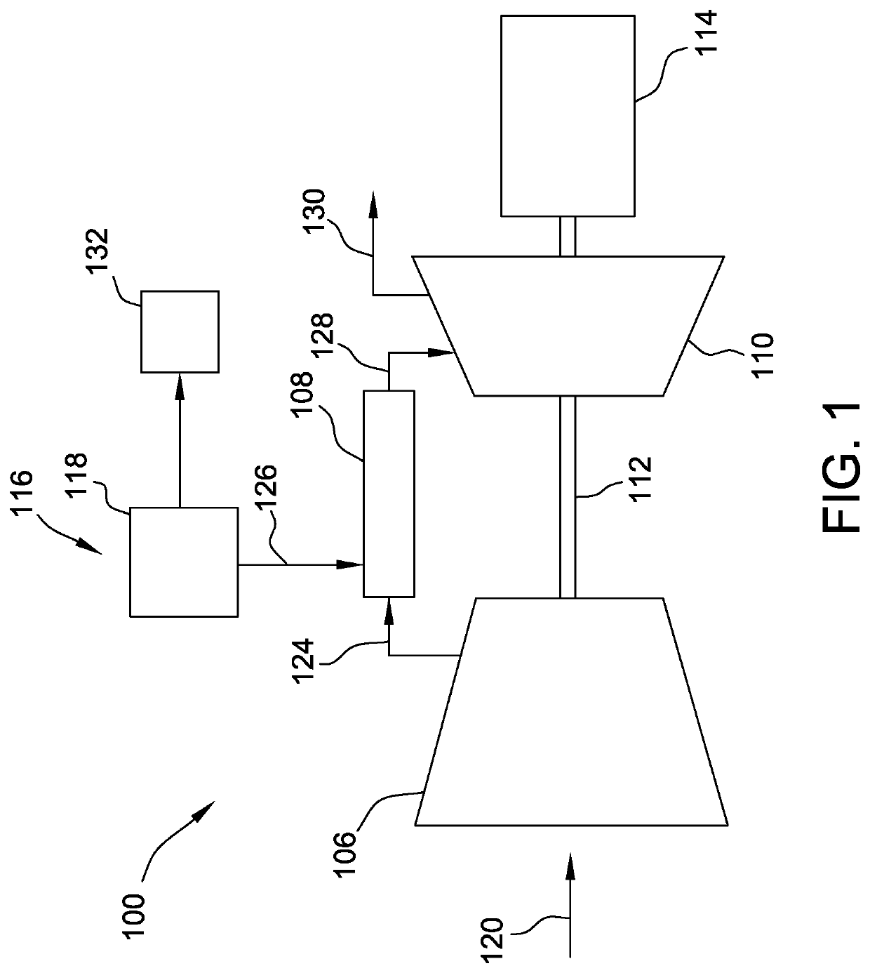
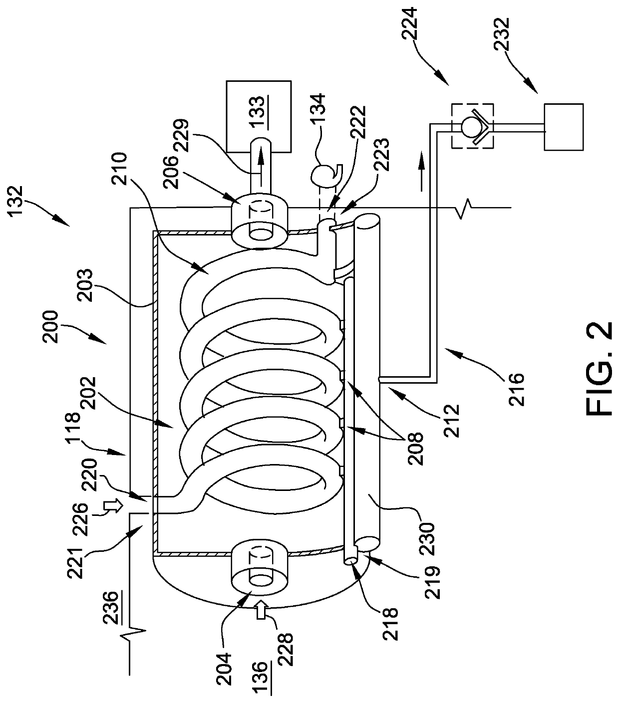
[0009]The exemplary systems and methods described herein include a dehumidifier assembly that does not require compression in order to dehumidify air sampled from an enclosure. The embodiments include an extraction chamber coupled in flow communication with the enclosure to receive sampled air, and a conduit positioned within the extraction chamber and sealed with respect to the extraction chamber. Ambient air is circulated through the conduit to provide a heat exchange medium for condensing moisture from the sampled air. The dehumidified air may then be provided at substantially atmospheric pressure to, for example, a gas detection device.

[0010]Unless otherwise indicated, approximating language, such as “generally,”“substantially,” and “about,” as used herein indicates that the term so modified may apply to only an approximate degree, as would be recognized by one of ordinary skill in the art, rather than to an absolute or perfect degree. Approximating language may be applied to mo...


PUM

PropertyMeasurementUnit
temperatureaaaaaaaaaa
atmospheric pressureaaaaaaaaaa
pressureaaaaaaaaaa

Abstract

A dehumidifier assembly includes an extraction chamber coupled in flow communication with a sample air inlet, a sample air outlet, and a sample drip opening. The extraction chamber is configured to receive a sample air flow therethrough at substantially atmospheric pressure from the sample air inlet to the sample air outlet. The dehumidifier assembly also includes a conduit positioned within the extraction chamber. The conduit is coupled in flow communication with an environmental air inlet and an environmental air outlet, and is sealed with respect to the extraction chamber. The dehumidifier assembly further includes a circulator coupled to the environmental air outlet. The circulator is operable to create a negative pressure in the conduit, such that an environmental air flow is drawn through the environmental air inlet into the conduit. The conduit is configured to facilitate heat transfer from the sample air flow to the environmental air flow.

Description

BACKGROUND[0001]The field of the disclosure relates generally to dehumidification and, more particularly, to an air dehumidifier assembly for use with a gas detection system.[0002]At least some known enclosures, such as, but not limited to, enclosures associated with a gas turbine, include a gas detection system to detect any potential gas leakage within the enclosure. For example, the gas turbine includes fuel gas control valves and fuel gas stop ratio valves housed in the enclosure, and the gas detection system is configured to examine air samples from the enclosure to detect any potential fuel gas leakage within the enclosure. A temperature and humidity of the air sample can vary due to, for example, a geographic location of the enclosure and / or seasonal changes. In some locations, a temperature of the air in the enclosure may drop below approximately 45 degrees Fahrenheit, for example. Such relatively low temperatures may cause moisture within the air to form into ice under air ...

Claims


Application Information

Patent Timeline
Patent Type & Authority Patents(United States)
IPC IPC(8): B01D49/00F24F3/14B01D51/00B01D50/00B01D41/00B01D45/00B01D46/00B01D39/00
CPCF24F3/14F24F2003/1446
Inventor AGUILAR, JOSE FRANCISCO
Owner GE INFRASTRUCTURE TECH INT LLC
Why Eureka
Try Eureka