Imaging device, focusing control method, and focusing control program

a technology of focusing control and focusing device, which is applied in the direction of camera focusing arrangement, printers, instruments, etc., can solve the problem of inability to improve the determination accuracy of the target position, and achieve the effect of high accuracy and speed

Active Publication Date: 2020-03-03
FUJIFILM CORP
View PDF33 Cites 0 Cited by
  • Summary
  • Abstract
  • Description
  • Claims
  • Application Information

AI Technical Summary

Benefits of technology

[0012]In order to perform the focusing control at a high speed through the contrast AF method, the movement speed of the focus lens at the time of a search operation when the focus lens is moved from a nearest end to an infinity end in order to acquire the evaluation values may be increased.
[0014]The increasing of the movement speed of the focus lens at the time of the search operation and the reducing of the sampling interval of the captured image signals during the movement of the focus lens (the increasing of the frame rate) are effective. However, in a case where the frame rate is increased, it is necessary to increase the movement speed of the focus lens with the increase in the frame rate.
[0017]In order to improve the determination accuracy of the target position, after the focus lens is moved from the nearest end to the infinity end, it is necessary to increase the number of evaluation values to be sampled by performing control such that the focus lens is returned from the infinity end to the nearest end in a state in which a desired value (a value at which a sufficient number of evaluation values is acquired) is set as the movement speed of the focus lens. However, in a case where this control is performed, a time taken to complete the focusing control is prolonged.
[0024]The present invention has been made in view of such circumstances, and an object of the present invention is to provide an imaging device, a focusing control method, and a focusing control program which are capable of constantly realizing focusing control at a high speed with high accuracy irrespective of being combined with a lens device.
[0028]According to the present invention, it is possible to provide an imaging device, a focusing control method, and a focusing control program which are capable of constantly realizing focusing control at a high speed with high accuracy irrespective of being combined with a lens device.

Problems solved by technology

Thus, determination accuracy of the target position is not able to be improved.

Method used


Image

  • Imaging device, focusing control method, and focusing control program
  • Imaging device, focusing control method, and focusing control program
  • Imaging device, focusing control method, and focusing control program

Examples


first modification example

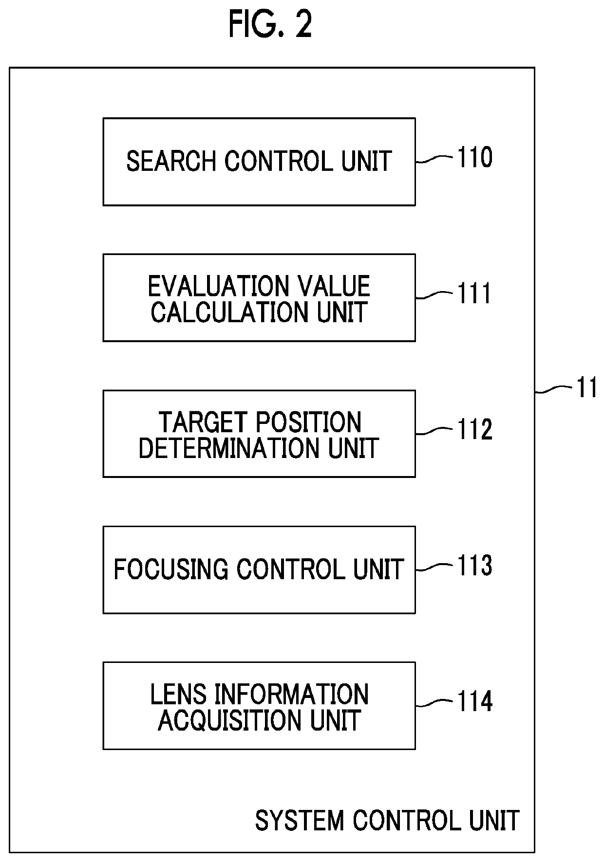
[0109]FIG. 5 is a diagram showing a modification example of a functional block of the system control unit 11 shown in FIG. 2.

[0110]The system control unit 11 shown in FIG. 5 is realized by adding a frame rate facc calculation unit 115 constituting a maximum imaging performance information calculation unit to the system control unit 11 shown in FIG. 2. The frame rate facc calculation unit 115 is formed by the focusing control program being executed by the processor.

[0111]Filter characteristic information of the filtering process performed in a case where the evaluation value calculation unit 111 calculates the evaluation values is further stored in the storage unit 12 of the digital camera according to the first modification example.

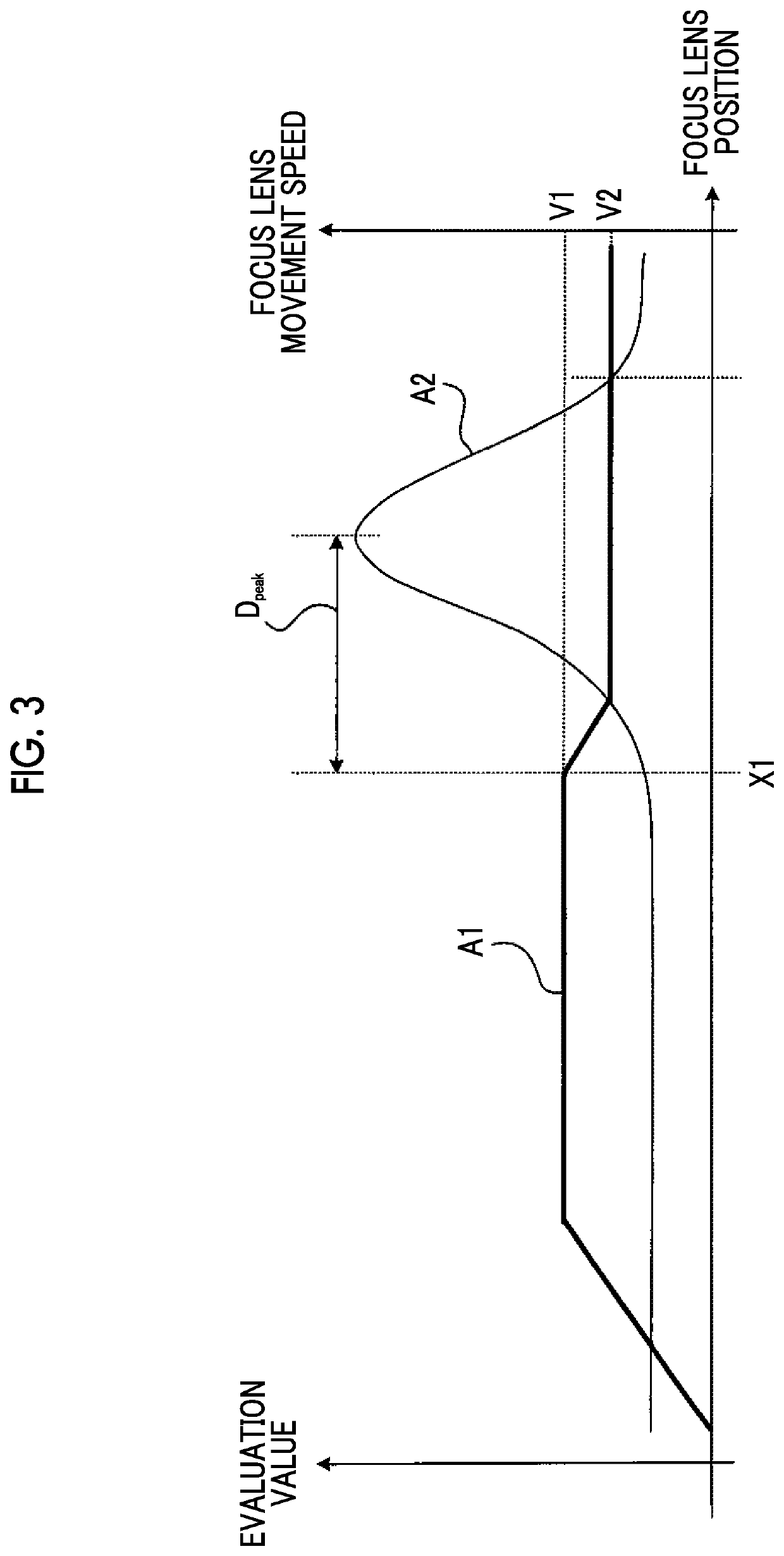
[0112]The filter characteristic information corresponds to a movement distance (distance Dpeak of FIG. 3) of the focus lens until the evaluation value reaches the peak after the change in evaluation value in the graph A2 shown in FIG. 3 which is equal to ...

second modification example

[0130]Although it has been described above that the priority specification information Pmode is included in the lens performance information, the lens performance information may not include the priority specification information Pmode. The operation of the system control unit 11 in this case will be described.

[0131]FIG. 7 is a flowchart for describing an operation of a system control unit 11 of a digital camera according to the second modification example. The flowchart shown in FIG. 7 is realized by removing step S5 and step S7 in the flowchart shown in FIG. 4 and performing step S6 in a case where the determination result of step S3 is YES.

[0132]For example, in a case where it is assumed that the lens device 40 is a short-focus lens and the frame rate fbody is greater than the frame rate facc, it is possible to determine the target position at a high speed with high accuracy in the combination of the frame rate fbody with the constant speed control compared to the combination of ...

third modification example

[0135]A third modification example is realized by applying the second modification example to the first modification example.

[0136]FIG. 8 is a flowchart for describing an operation of a system control unit 11 of a digital camera according to the third modification example.

[0137]The flowchart shown in FIG. 8 is realized by removing step S5 and step S7 in the flowchart shown in FIG. 6 and performing step S6 in a case where the determination result of step S3 is YES.

[0138]For example, in a case where it is assumed that the lens device 40 is a short-focus lens and the frame rate fbody is greater than the frame rate facc, it is possible to determine the target position at a high speed with high accuracy in the combination of the frame rate fbody with the constant speed control compared to the combination of the frame rate facc with the acceleration and deceleration control.

[0139]In a case where the frame rate fbody is sufficiently greater than the frame rate facc even though it is assume...


PUM


Abstract

An imaging device to which a lens device including a focus lens capable of moving in an optical axis direction is detachably attached, includes: an imaging element; a search control unit; an evaluation value calculation unit; a target position determination unit; a focusing control unit; a storage unit; and a lens information acquisition unit, as defined herein, and the search control unit selectively performs one of acceleration and deceleration control such that a movement speed of the focus lens is decelerated after the movement speed is accelerated and constant speed control such that the movement speed of the focus lens is constant by controlling the movement speed based on the evaluation values, based on the lens performance information and the first imaging performance information.

Description

CROSS REFERENCE TO RELATED APPLICATION[0001]This is a continuation of International Application No. PCT / JP2016 / 082696 filed on Nov. 2, 2016, and claims priority from Japanese Patent Application No. 2015-249618 filed on Dec. 22, 2015, the entire disclosures of which are incorporated herein by reference.BACKGROUND OF THE INVENTION[0002]1. Field of the Invention[0003]The present invention relates to an imaging device, a focusing control method, and a computer readable medium storing a focusing control program.[0004]2. Description of the Related Art[0005]In recent years, with an increase in resolution of imaging elements, such as a charge coupled device (CCD) image sensor and a complementary metal oxide semiconductor (CMOS) image sensor, there has been a rapid increase in demand for information devices having an imaging function, such as a digital still camera, a digital video camera, and a smartphone. The information devices having an imaging function described above are referred to as...

Claims


Application Information

Patent Timeline
Patent Type & Authority Patents(United States)
IPC IPC(8): G02B7/36G03B17/14H04N5/232G03B3/10G03B13/36H04N5/225G02B7/04
CPCH04N5/23212G02B7/36G02B7/04H04N5/232G03B3/10G03B17/14H04N5/2254G03B13/36H04N23/67H04N23/55
Inventor PAN, YI
Owner FUJIFILM CORP
Why Eureka
Try Eureka