Imaging device, focusing control method, and focusing control program
a technology of focusing control and focusing device, which is applied in the direction of camera focusing arrangement, printers, instruments, etc., can solve the problem of inability to improve the determination accuracy of the target position, and achieve the effect of high accuracy and speed
- Summary
- Abstract
- Description
- Claims
- Application Information
AI Technical Summary
Benefits of technology
Problems solved by technology
Method used
Image
Examples
first modification example
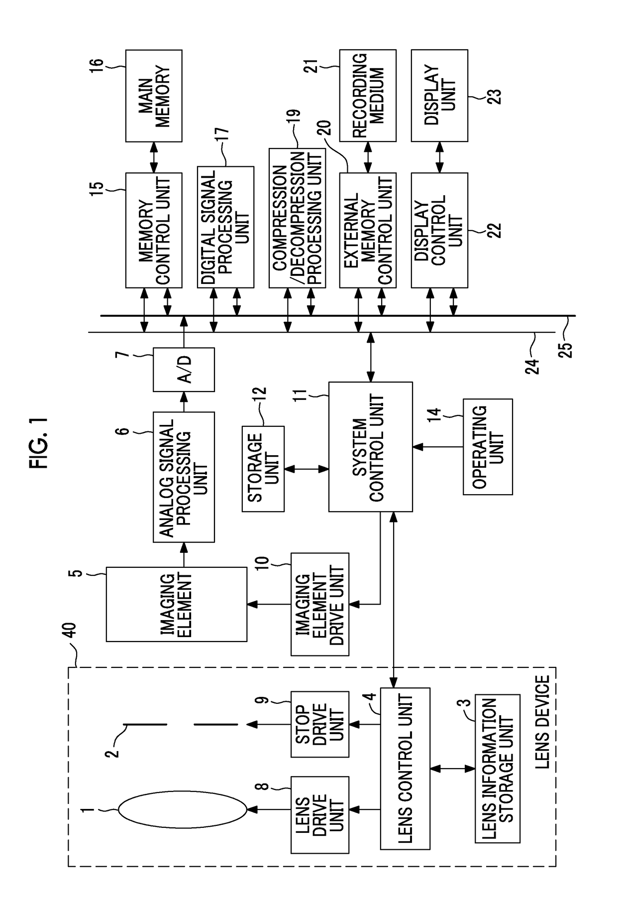
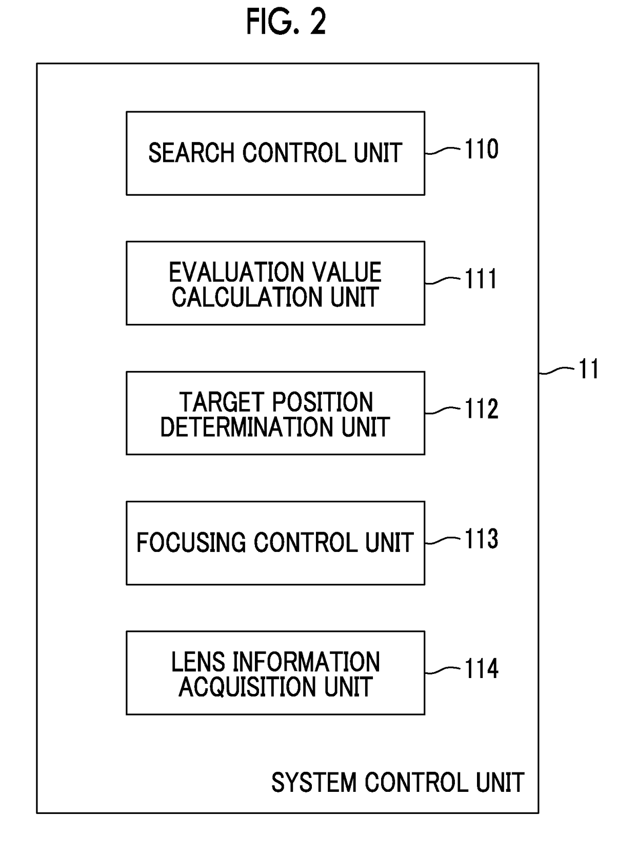
[0107]FIG. 5 is a diagram showing a modification example of a functional block of the system control unit 11 shown in FIG. 2.
[0108]The system control unit 11 shown in FIG. 5 is realized by adding a frame rate facc calculation unit 115 constituting a maximum imaging performance information calculation unit to the system control unit 11 shown in FIG. 2. The frame rate facc calculation unit 115 is formed by the focusing control program being executed by the processor.
[0109]Filter characteristic information of the filtering process performed in a case where the evaluation value calculation unit 111 calculates the evaluation values is further stored in the storage unit 12 of the digital camera according to the first modification example.
[0110]The filter characteristic information corresponds to a movement distance (distance Dpeak of FIG. 3) of the focus lens until the evaluation value reaches the peak after the change in evaluation value in the graph A2 shown in FIG. 3 which is equal to ...
second modification example
[0127]Although it has been described above that the priority specification information Pmode is included in the lens performance information, the lens performance information may not include the priority specification information Pmode. The operation of the system control unit 11 in this case will be described.
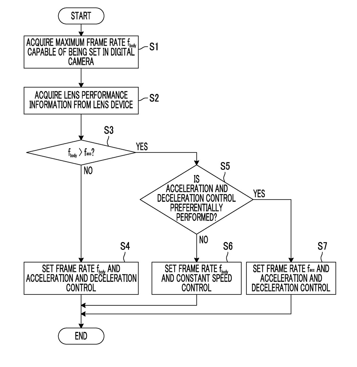
[0128]FIG. 7 is a flowchart for describing an operation of a system control unit 11 of a digital camera according to the second modification example. The flowchart shown in FIG. 7 is realized by removing step S5 and step S7 in the flowchart shown in FIG. 4 and performing step S6 in a case where the determination result of step S3 is YES.
[0129]For example, in a case where it is assumed that the lens device 40 is a short-focus lens and the frame rate fbody is greater than the frame rate facc, it is possible to determine the target position at a high speed with high accuracy in the combination of the frame rate fbody with the constant speed control compared to the combination of ...
third modification example
[0132]A third modification example is realized by applying the second modification example to the first modification example.
[0133]FIG. 8 is a flowchart for describing an operation of a system control unit 11 of a digital camera according to the third modification example.
[0134]The flowchart shown in FIG. 8 is realized by removing step S5 and step S7 in the flowchart shown in FIG. 6 and performing step S6 in a case where the determination result of step S3 is YES.
[0135]For example, in a case where it is assumed that the lens device 40 is a short-focus lens and the frame rate fbody is greater than the frame rate facc, it is possible to determine the target position at a high speed with high accuracy in the combination of the frame rate fbody with the constant speed control compared to the combination of the frame rate facc with the acceleration and deceleration control.
[0136]In a case where the frame rate fbody is sufficiently greater than the frame rate facc even though it is assume...
PUM
 Abstract
Description
Claims
Application Information
 - R&D
- Intellectual Property
- Life Sciences
- Materials
- Tech Scout
- Unparalleled Data Quality
- Higher Quality Content
- 60% Fewer Hallucinations
Browse by: Latest US Patents, China's latest patents, Technical Efficacy Thesaurus, Application Domain, Technology Topic, Popular Technical Reports.
© 2025 PatSnap. All rights reserved.Legal|Privacy policy|Modern Slavery Act Transparency Statement|Sitemap|About US| Contact US: help@patsnap.com


