
Continuous serpentine concrete beamway forming system and a method for creating a hollow continuous serpentine concrete beamway

Active Publication Date: 2020-03-10
WARD DAVID RALPH
View PDF6 Cites 6 Cited by
  • Summary
  • Abstract
  • Description
  • Claims
  • Application Information

AI Technical Summary

Benefits of technology

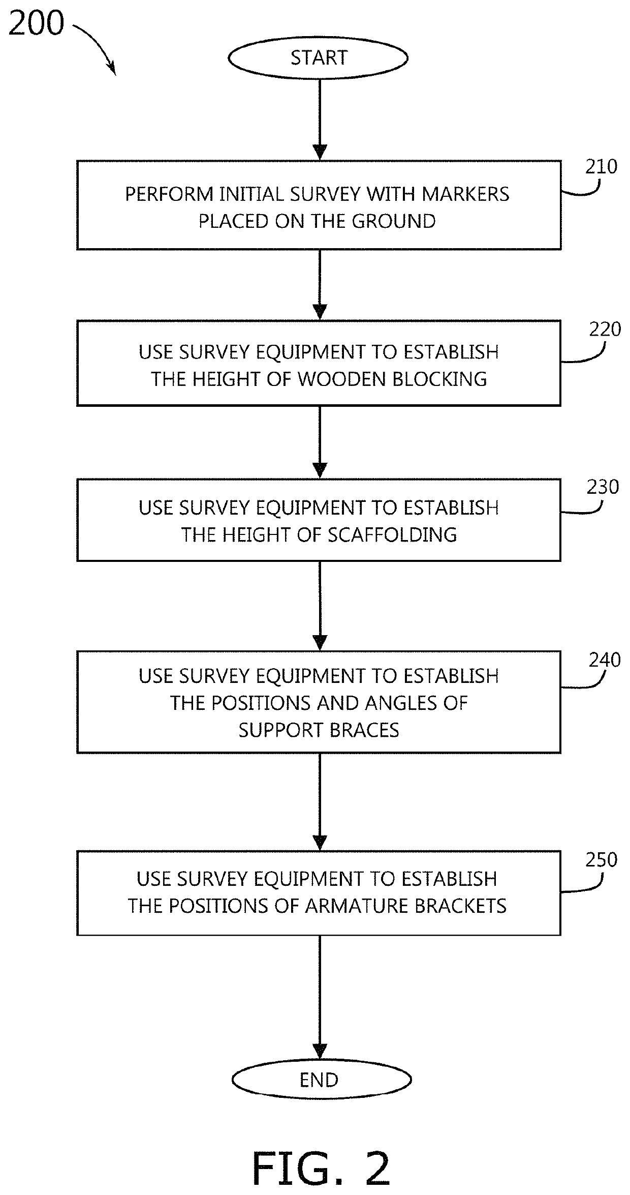
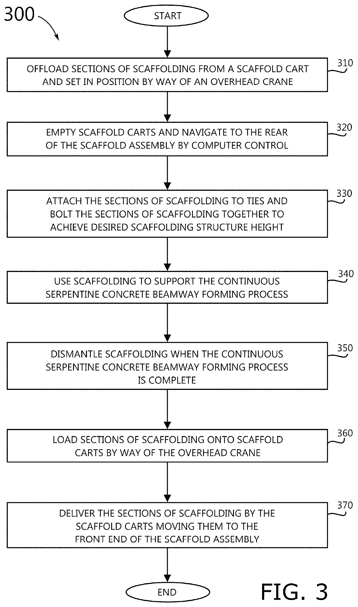
This patent describes a system and method for creating a hollow continuous serpentine concrete beamway. The system includes a flexible form material that can conform to the curves, angles, and slopes of the beamway system. This material is used to form an armature that aligns precisely with the target beamway system. The armature has grooves on its surface that guide the grinding machines used to grind the beamway surfaces to precise tolerances. The method involves initial surveying, ground interface procedures, scaffold erection, tray adjustments, and the use of form material to create the armature structure. The form material is then used to print concrete sides and the top of the beamway rail, remove the beamway forming apparatus, and dress the beamway rails. The technical effect of this patent is the creation of a precise and hollow continuous serpentine concrete beamway that is aligned with the target beamway system and has grooves for accurate grinding.

Problems solved by technology

This process is expensive and time-consuming.
The beamways created in this fashion contain irregularities in the surfaces of the beamways, as well as the potential for misalignment in the joints between the beamway sections.

Method used


Image

  • Continuous serpentine concrete beamway forming system and a method for creating a hollow continuous serpentine concrete beamway
  • Continuous serpentine concrete beamway forming system and a method for creating a hollow continuous serpentine concrete beamway
  • Continuous serpentine concrete beamway forming system and a method for creating a hollow continuous serpentine concrete beamway

Examples


Embodiment Construction

[0035]In the following detailed description of the invention, numerous details, examples, and embodiments of the invention are described. However, it will be clear and apparent to one skilled in the art that the invention is not limited to the embodiments set forth and that the invention can be adapted for any of several applications.

[0036]Some embodiments of the invention include a novel continuous serpentine concrete beamway forming system and a novel method for creating a hollow continuous serpentine concrete beamway. In some embodiments, the continuous serpentine concrete beamway forming system and method for creating a hollow continuous serpentine concrete beamway utilizes a flexible form material that has the ability to conform to curves, angles, and slopes of a target beamway system as intended. In some embodiments, the flexible form material is used to form an armature that embodies a precise pathway of the target beamway system. In some embodiments, the armature is contiguo...


PUM


Abstract

A continuous serpentine concrete beamway forming system and method for creating a hollow continuous serpentine concrete beamway are disclosed. The continuous serpentine concrete beamway forming system and method utilizes a flexible form material that has the ability to conform to curves, angles, and slopes of a target beamway system as intended. The flexible form material is used to form an armature that embodies a precise pathway of the target beamway system. The armature is contiguous throughout a plurality of connected beamway segments that collectively make up the target beamway system and that are precisely aligned to conform to the curves, angles, and slopes of the target beamway system. A part of the armature creates grooves on the surfaces of the connected beamway segments. The grooves are subsequently used to guide machinery that grinds the running surfaces to precise tolerances. Precise alignment is achieved as a result of the grooves being formed in a continuous fashion, thereby allowing the grinding machines to cross from one beamway segment to the next.

Description

CLAIM OF BENEFIT TO PRIOR APPLICATION[0001]This application claims benefit to U.S. Provisional Patent Application 62 / 473,123, entitled “A mechanism for creating elevated rails for monorail vehicles,” filed Mar. 17, 2017. The U.S. Provisional Patent Application 62 / 473,123 is incorporated herein by reference.BACKGROUND[0002]Embodiments of the invention described in this specification relate generally to rail building systems, and more particularly, to a continuous serpentine concrete beamway forming system and a method for creating a hollow continuous serpentine concrete beamway suitable for high-speed monorail traffic and other transit profiles, including, without limitation, transit guideways, bike paths, sidewalks, and architectural features.[0003]Existing methods for creating concrete beamways suitable for monorail type transit, involve precasting the beamways offsite, then transporting the completed beamways to the installation site. Heavy equipment is required to set the beamway...

Claims


Application Information

Patent Timeline
IPC IPC(8): E01B35/10B61B13/04E01B25/10E01B25/24E01B35/02
CPCE01B35/02E01B25/10B61B13/04E01B25/24E01B35/10E01B2204/15E01B25/08E01B25/305E01B25/32E01B2203/16
Inventor WARD, DAVID RALPH
Owner WARD DAVID RALPH
Features
  • Generate Ideas
  • Intellectual Property
  • Life Sciences
  • Materials
  • Tech Scout
  • Unparalleled Data Quality
  • Higher Quality Content
  • 60% Fewer Hallucinations
Learn More