Electrode for radiofrequency tissue ablation

a radiofrequency tissue and electrode technology, applied in the field of electrodes for electric operation devices, can solve the problems of excessive ablation and carbonization of living tissue adjacent to electrodes and blood, limited volume of saline solution infused into living tissue, and detrimental effects on patients, so as to reduce the ablation and necrosis time of living tissue and expand the ablation zone of living tissue.

Inactive Publication Date: 2006-06-08
JUN MYONG KI
View PDF39 Cites 87 Cited by
  • Summary
  • Abstract
  • Description
  • Claims
  • Application Information

AI Technical Summary

Benefits of technology

[0007] The present invention is achieved to solve the above problems. An object of the present invention is to provide an electrode for an electric operation device which can enlarge an ablation zone of a living tissue and reduce an ablation and necrosis time of the living tissue, by supplying an electrode structure using both a method for cooling the inside of the electrode by a saline solution and a method for directly discharging the saline solution to the living tissue.

Problems solved by technology

However, the living tissue adjacent to the electrode and blood are excessively ablated and carbonized.
However, when a large volume of saline solution is infused into the living tissue, it has detrimental effects on patients.
Therefore, the volume of the saline solution infused into the living tissue is restricted.
As a result, the ablation zone is not efficiently enlarged.
However, when the RF energy exceeding the limit point is generated, the tissue adjacent to the electrode is carbonized, and thus the ablation zone is not efficiently enlarged.

Method used


Image

  • Electrode for radiofrequency tissue ablation
  • Electrode for radiofrequency tissue ablation
  • Electrode for radiofrequency tissue ablation

Examples


example

[0042] An experimental object was a cow liver, and an RF generator was a 480-kHz RF generator (Radionics, USA). 5.85% of saline solution was supplied in the electrode at a rate of 80 to 120 ml / min, and infused into the living tissue at a rate of 1 ml / cm. An ablation and necrosis experiment was executed 50 times by sequentially supplying the outputs of 30 sec-1.2 A (about 120 W), 30 sec-1.6 A (about 160 W) and 12˜15 sec-2 A (about 200 W), and maintaining an impedance between 50 and 110Ω. An ablation and necrosis zone was measured by the MRI.

[0043] Here, a thermocouple was embedded in the electrode. A temperature of the living tissue adjacent to the electrode was measured by an impedance of the thermocouple, and the RF power and current applied to the electrode were controlled according to the measured temperature, thereby preventing the living tissue from being excessively heated and carbonized, and performing ablation and necrosis on the living tissue in the wider zone.

[0044] Gene...


PUM


Abstract

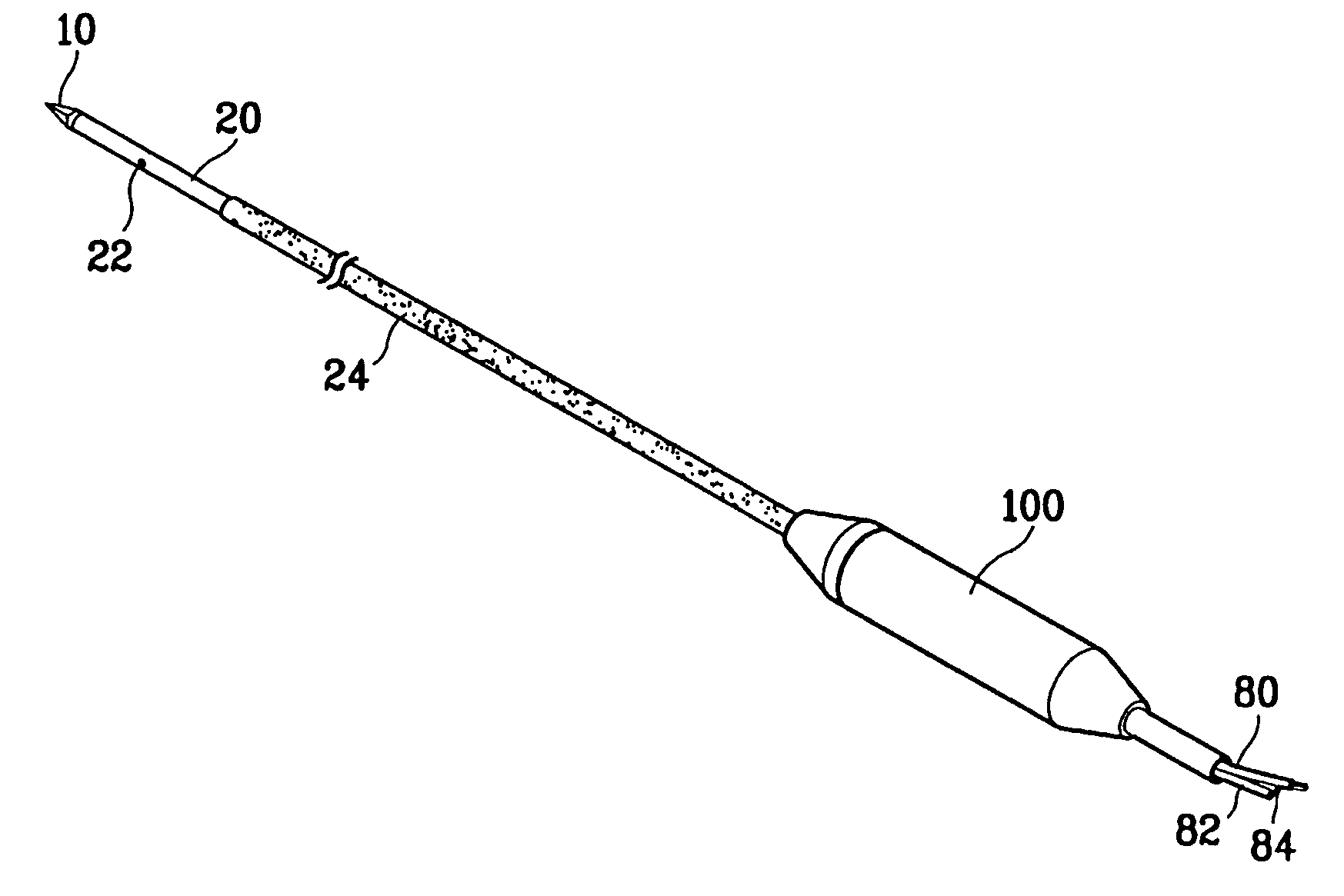
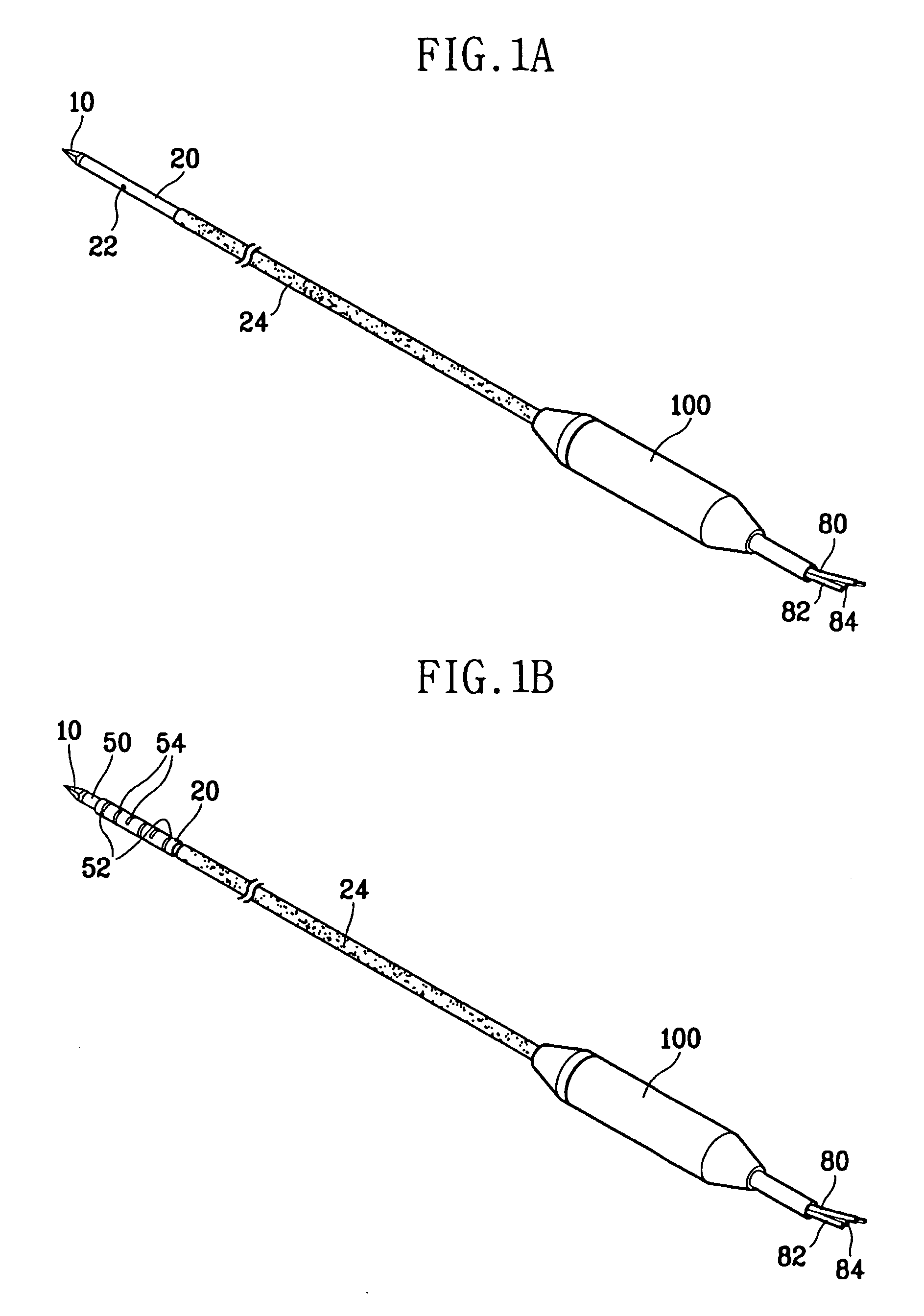
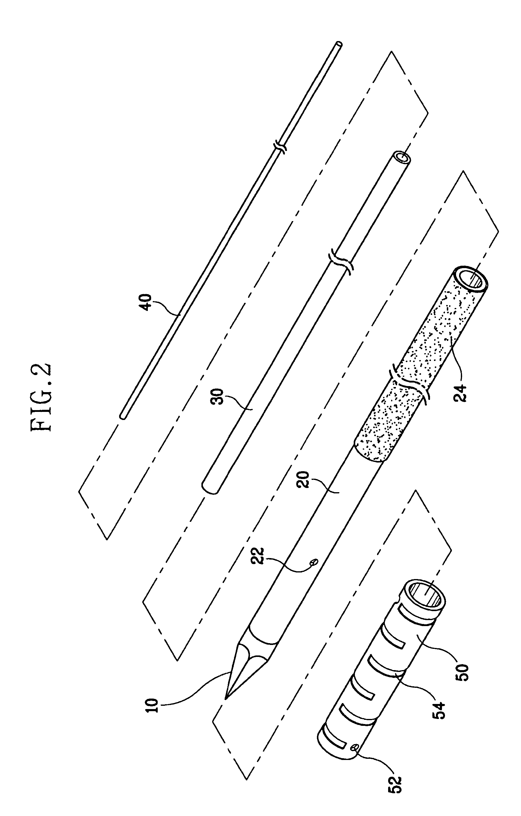
The present invention discloses an electrode for an electric operation device including a hollow electrode being formed in a hollow tube shape extended long from a closed tip, and having an insulation-coating on the outside surface except a predetermined length of the closed tip side, a refrigerant tube having a smaller diameter than a diameter of the hollow electrode, and being inserted into the hollow electrode, the refrigerant tube supplying refrigerants for cooling a living tissue contacting the closed tip and the hollow electrode into the hollow electrode, and externally discharging the heat-exchanged refrigerants from the living tissue through the gap between the refrigerant tube and the hollow electrode, at least one first hole formed on the outside surface of the hollow electrode where the insulation coating has not been formed, for externally discharging some of the refrigerants supplied through the refrigerant tube from the hollow electrode, and a flow control means formed on the outside surface of the hollow electrode where the insulation coating has not been formed, and operated as a discharge resistance to the refrigerants discharged from the first hole, for controlling a flow of the refrigerants, whereby supplying an electrode structure using both a method for water-cooling the inside of the electrode and a method for discharging the saline solution.

Description

TECHNICAL FIELD [0001] The present invention relates to an electrode for an electric operation device, and more particularly to, an electrode for an electric operation device for ablation and necrosis of a living tissue using RF electric energy. BACKGROUND ART [0002] In general, a technique of ablating (or coagulating) a wanted living tissue with RF energy by inserting a long hollow tube-shaped electrode into the living tissue has been publicly known. When current is applied to the living tissue, the living tissue is heated, and thus the living tissue and blood vessels are ablated by a complicated biochemical process. This process depends on ablation of a cell by thermal transformation of cell proteins over about 60° C. Here, the cell implies the tissue, blood vessel and blood. However, the living tissue adjacent to the electrode and blood are excessively ablated and carbonized. The carbonized living tissue adjacent to the electrode is operated as an insulator, namely an obstacle to...

Claims


Application Information

Patent Timeline
Patent Type & Authority Applications(United States)
IPC IPC(8): A61B18/14A61B18/16A61B18/00
CPCA61B18/1477A61B2018/00023A61B2018/00029A61B2018/00083A61B2218/002A61B18/16
Inventor JUN, MYONG-KI
Owner JUN MYONG KI
Why Eureka
Try Eureka