
Method for manufacturing a spark plug, and spark plug

a manufacturing method and technology for spark plugs, applied in the manufacture of spark plugs, spark plugs, manufacturing tools, etc., can solve the problems of insufficient penetration depth d of weld metal parts, affecting the durability of spark plugs, and affecting the performance of spark plugs, etc., to achieve the effect of suppressing spattering, increasing the energy density of laser beams, and small amount of laser beam heat inpu

Inactive Publication Date: 2006-02-14
NGK SPARK PLUG CO LTD
View PDF12 Cites 17 Cited by
  • Summary
  • Abstract
  • Description
  • Claims
  • Application Information

AI Technical Summary

Benefits of technology

The present invention provides a method for manufacturing a spark plug with a noble metal chip, center electrode, and ground electrode. The method involves laser-beam-welding the chip to the center electrode or the ground electrode at a position corresponding to a spark discharge gap. The method includes using a graded-index-type fiber optic cable as an optical transmission path, which increases the energy density of the laser beam and allows for better penetration depth and reduced spattering. The method also involves aligning the laser beam with the weld metal portion to enhance the spark ablation resistance of the spark plug. Overall, the method provides a more efficient and effective way to manufacture spark plugs.

Problems solved by technology

As a result, a problem such as misfire arises; i.e., a problem of impaired durability of the spark portion 31 arises.
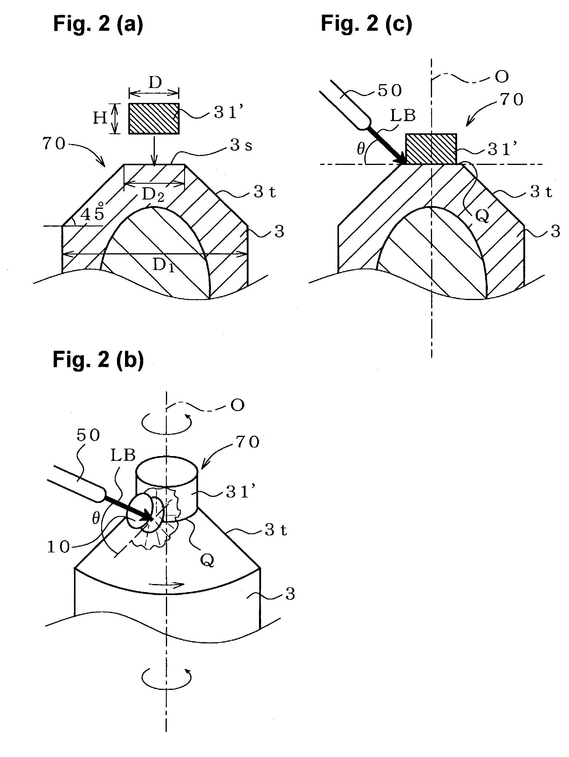
But, in some cases the penetration depth d of the weld metal portion 10—which is formed in such a manner as to intrude into a chip joint face formation portion of the electrode 3 and into the noble metal chip 31′—may be insufficient.

Method used


Image

  • Method for manufacturing a spark plug, and spark plug
  • Method for manufacturing a spark plug, and spark plug
  • Method for manufacturing a spark plug, and spark plug

Examples


Embodiment Construction

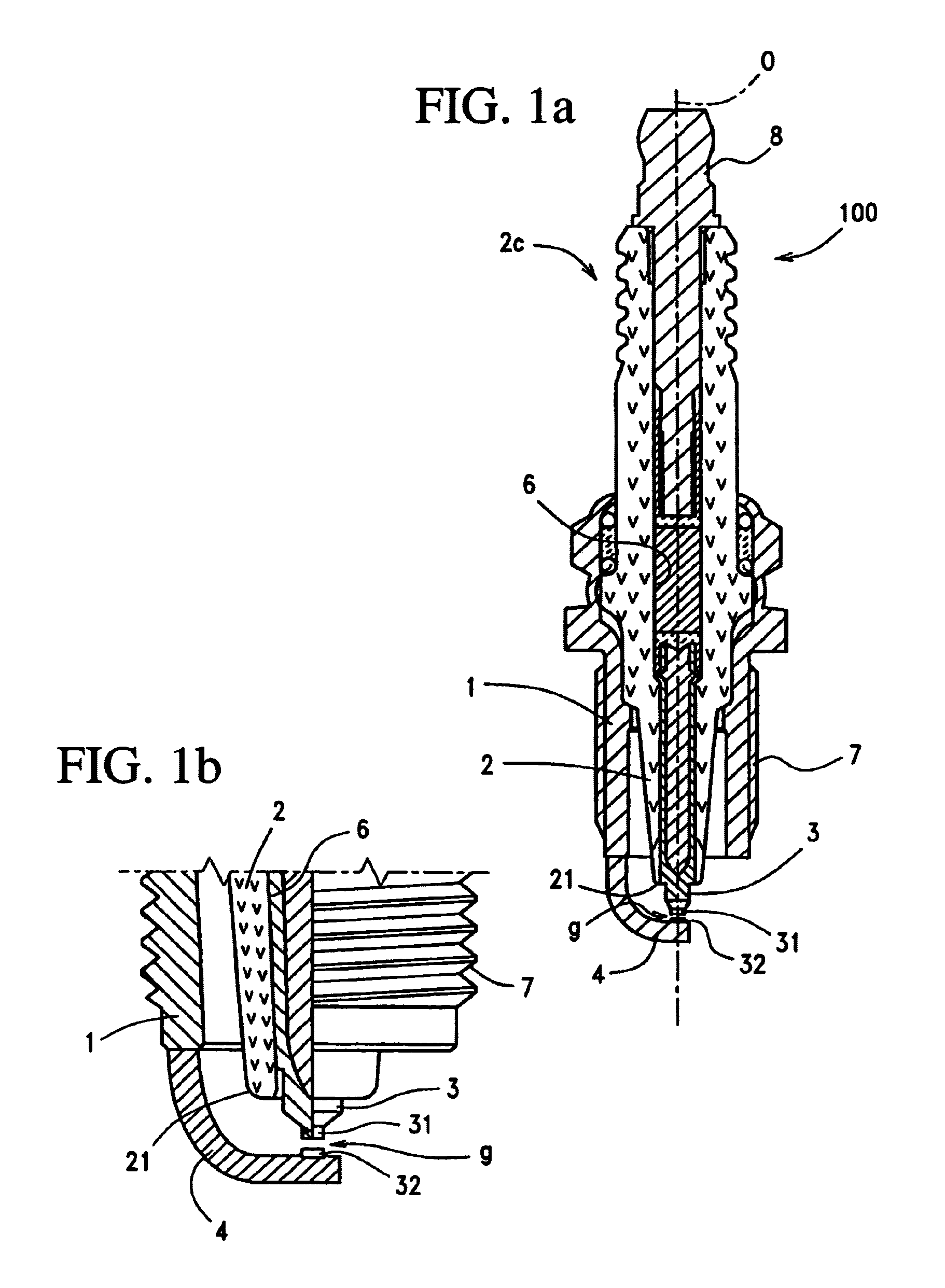
[0057]The preferred embodiments of the present invention will now be described in connection with the accompanying drawings. Referring now to FIG. 1, a spark plug 100 includes a tubular metallic shell 1, an insulator 2 fitted into the metallic shell 1 so that its distal end portion 2 projects from the metallic shell 1. A center electrode 3 is disposed inside the insulator 2 so that a noble-metal spark portion (hereinafter sometimes referred to as a “spark portion”) 31 formed at its distal end projects from the insulator 2. A ground electrode 4 includes one end joined to the metallic shell 1 by means of welding or a like process and a second end portion bent such that the side surface thereof faces a distal end portion of the center electrode 3. A noble-metal spark portion 32 is formed on the ground electrode 4 in such a manner as to face the spark portion 31. The gap between the opposed spark portions 31 and 32 serves as a spark discharge gap 9.

[0058]Herein, the “spark portion” deno...


PUM

PropertyMeasurementUnit
diameteraaaaaaaaaa
angleaaaaaaaaaa
angleaaaaaaaaaa

Abstract

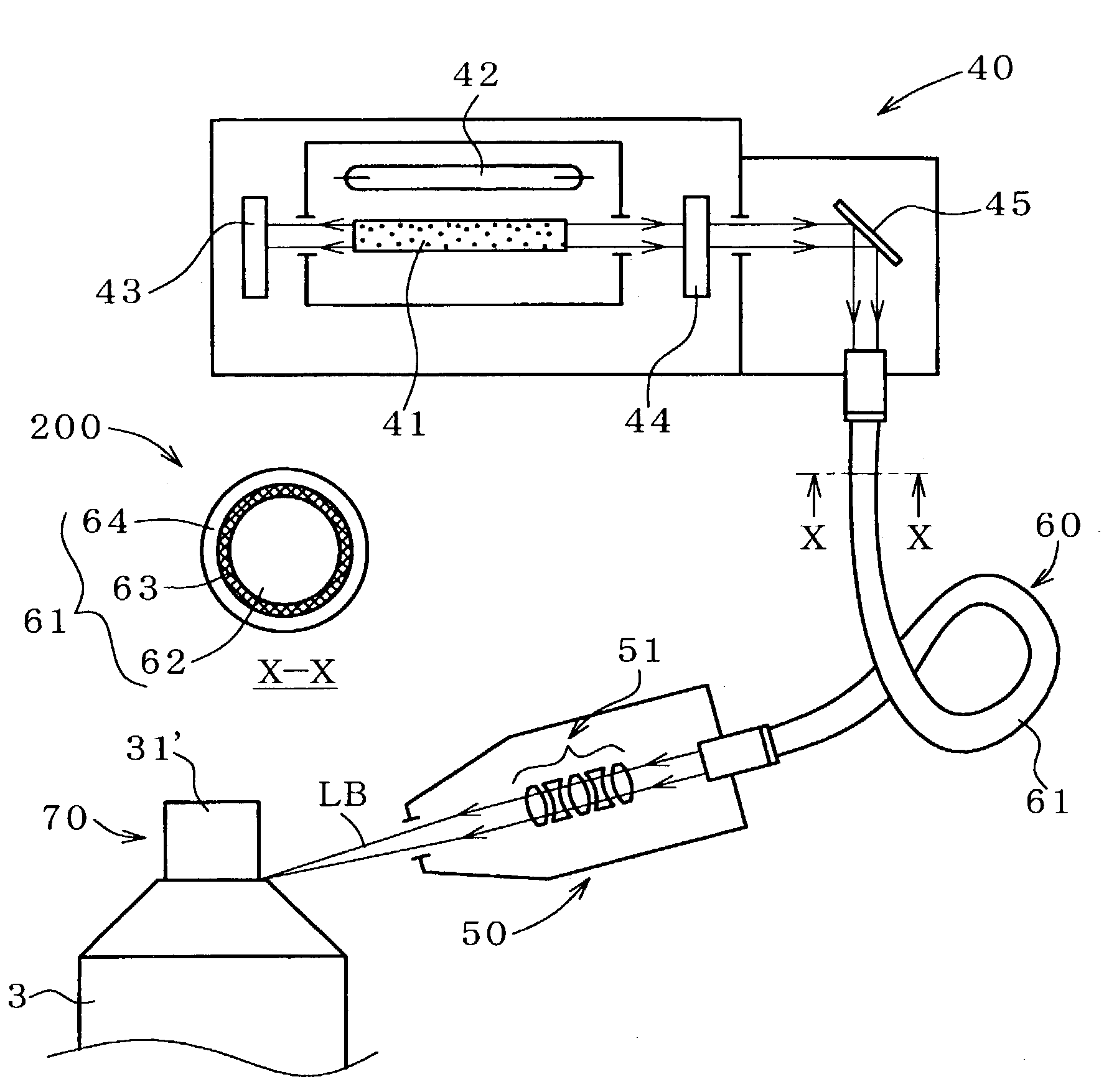
A method for manufacturing a spark plug which reduces the generation of spatters and the possibility of insufficient weld strength resulting from penetration depth insufficiency of a weld metal portion is disclosed. In accordance with the method, a chip joint face formation portion of a center electrode is formed from a heat-resistant alloy predominantly containing Fe or Ni. A noble metal chip is attached to a chip joint face of the chip joint face formation portion to thereby form a chip-attached assembly. A full-circled laser-beam weld metal portion is formed on the chip-attached assembly in such a manner as to intrude into the noble metal chip and into the chip joint face formation portion. A graded-index-type fiber optic cable is used as an optical transmission path extending between a laser beam generator and an optical emission section. A laser beam which is transmitted from the laser beam generator through the cable irradiates the chip-attached assembly while being condensed.

Description

FIELD OF THE INVENTION[0001]The present invention relates to a method for manufacturing a spark plug and to a spark plug and more particularly to a method for manufacturing a spark plug wherein a noble metal chip is laser-beam welded to an electrode and to a spark plug manufactured by such method.BACKGROUND FOR THE INVENTION[0002]In order to enhance spark ablation resistance of a spark plug used for providing ignition in an internal combustion engine, one type of spark plug employs a noble-metal spark portion formed by means of welding a noble metal chip to a distal end of an electrode that is formed from a Ni- or Fe-based heat resistant alloy. The noble metal chip predominantly contains Pt, Ir, or the like.[0003]A method for joining a noble-metal chip to the distal end face of a center electrode to form a spark discharge gap in cooperation with an opposed ground electrode, includes the step of making a full-circled laser-beam weld. For example, see Japanese Patent Application Laid-...

Claims


Application Information

Patent Timeline
Patent Type & Authority Patents(United States)
IPC IPC(8): H01T21/02B23K26/00H01T13/39
CPCH01T21/02H01T13/39
Inventor TANIGUCHI, YUTAKASUMI, MASAHIDESAKURA, AKIO
Owner NGK SPARK PLUG CO LTD
Learn More