Fiber optic infrared laser beam delivery system

a fiber optic infrared and laser beam technology, applied in the direction of yarn, lasers, instruments, etc., can solve the problems of large core silica fiber that cannot be used in high beam quality processes, fused silica fiber is limited to transmission, and cannot be used in laser beam delivery outside, so as to reduce the level of heat, high thermal conductivity, and high reflectivity

Active Publication Date: 2006-08-29
CHENARD FRANCOIS
View PDF9 Cites 84 Cited by
  • Summary
  • Abstract
  • Description
  • Claims
  • Application Information

AI Technical Summary

Benefits of technology

[0024]The HC-PBG fiber normally has a quasi-Gaussian fundamental mode field distribution. It can be made of materials such as chalcogenide glass, germanate glass, phosphate glass, telluride glass, borate glass, antimonate glass and halide glass, with the preferred material being chalcogenide glass. It is held in proper position by means of a suitable holding fixture which surrounds and supports the input end of the HC-PBG fiber. Preferably, the HC-PBG fiber is supported by the holding fixture beyond the beam admitting end, to reduce the level of heat at the holding location; thus, the HC-PBG fiber projects out of the holding fixture over a small distance at the input end, typically one millimeter, although this projection may take place within a central recess formed in the holding fixture. The HC-PBG fiber may be of any desired design. For example, it can have a hollow core in the form of a longitudinal central opening, a microstructured periodically cladding region with a plurality of longitudinal surrounding openings and a jacket, plus a soft protective coating which is removed from the end of the fiber cable when it is inserted into the holding fixture. It can also be of a design where the periodically cladding regio

Problems solved by technology

But large core silica fiber cannot currently be used for high beam quality processes because of the highly multimode nature of these fibers.
Furthermore, as is known, fused silica fiber is limited to transmission in the wavelength range of about 0.2 to 2 μm, and cannot be used in laser beam delivery outside this range.
However, transmission losses of the HGW fiber vary as 1/a3 where a is the bore radius and, therefore, the loss can be arbitrarily small for a sufficiently large core (300–1000 μm).
Another disadvantage of the HGW fiber is the added loss on bending which is also polarization sensitive.
But none of them can transmit efficiently stable high power

Method used


Image

  • Fiber optic infrared laser beam delivery system
  • Fiber optic infrared laser beam delivery system
  • Fiber optic infrared laser beam delivery system

Examples


Embodiment Construction

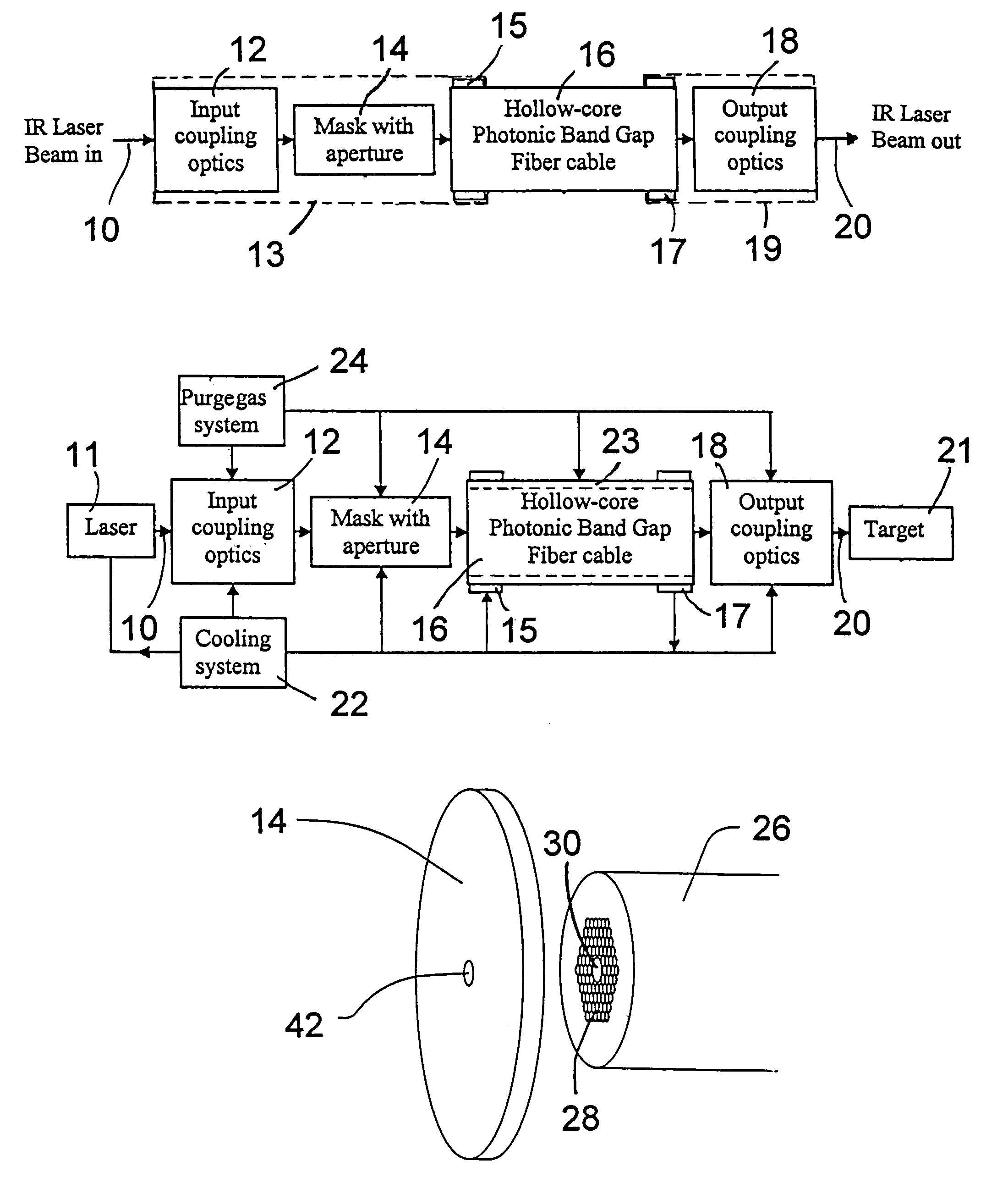
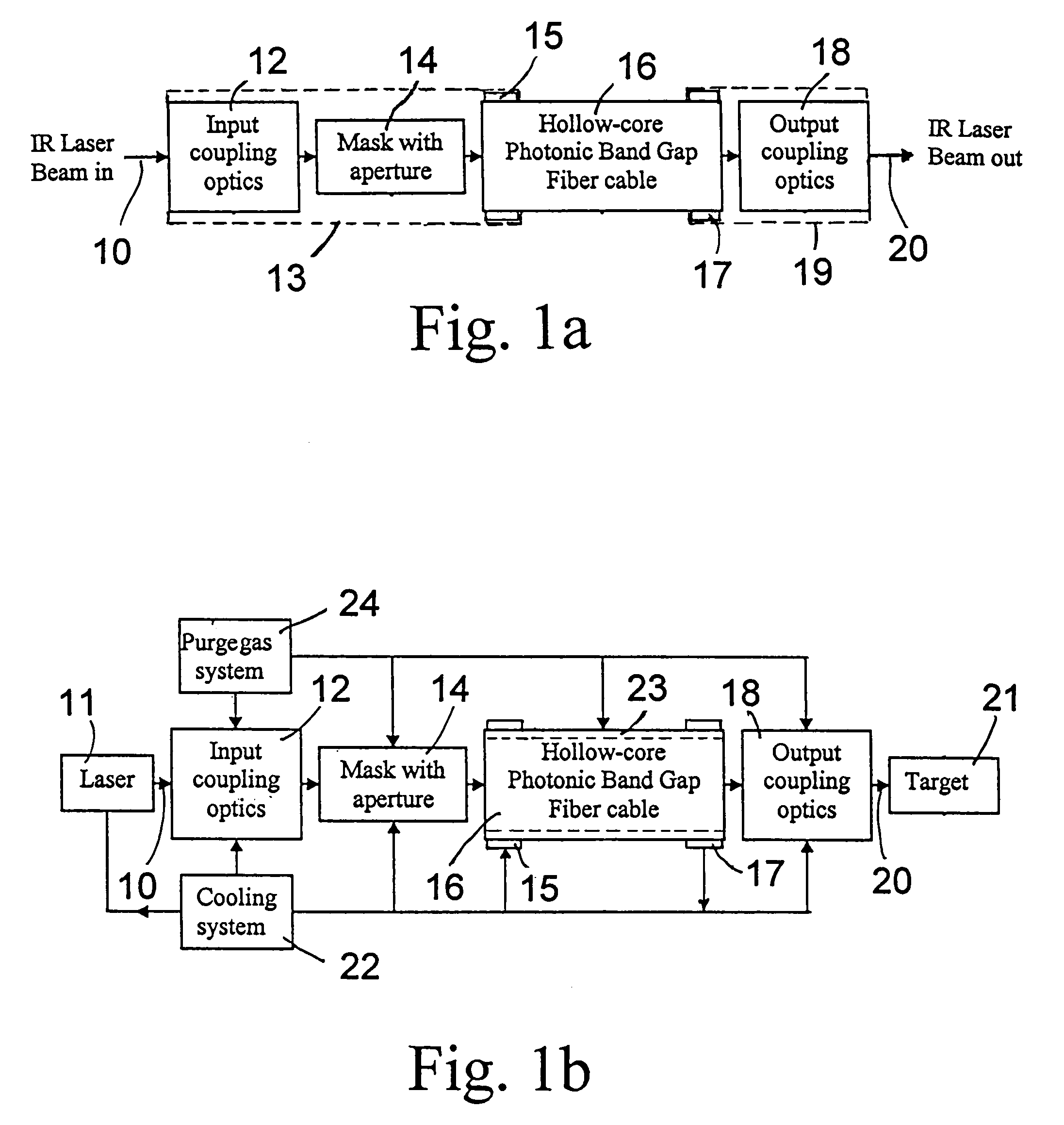
[0036]In the drawings in which the same elements are designated by the same reference numbers, FIG. 1a is a block diagram illustrating the basic fiber optic laser beam delivery system of the present invention. As illustrated in this figure, an infrared (IR) laser beam is projected, as shown by arrow 10, into input coupling optics 12 by which the beam is focused so as to pass through the aperture of the mask 14 and be coupled into the hollow-core photonic band gap (HC-PBG) fiber cable 16. The HC-PBG fiber cable 16 may have a length typically ranging from one meter to several hundred meters. The IR laser beam is transmitted through and exits the HC-PBG fiber cable 16 into output coupling optics 18 from which it emerges as shown by arrow 20. The output coupling optics are adapted to collimate the output IR laser beam and eventually to focus it onto a desired target spot. In order to maintain satisfactory alignment between the various components, it is preferable that the input coupling...


PUM


Abstract

A laser beam delivery system is disclosed, which allows transmission of high-power infrared light through a hollow core photonic band gap (HC-PBG) fiber made of non-silica-based glass. In this system, the infrared beam first passes through input coupling optics which focus the beam onto the hollow core of the HC-PBG fiber. In front of the input end of the HC-PBG fiber, there is provided a mask with a hole aligned with the hollow core, and the infrared beam first passes through this hole before entering the hollow core of the HC-PBG fiber. This protects the photonic band gap structure from being damaged by the beam. After passing through the HC-PBG fiber, which may be from one to several hundred meters in length, the infrared beam exits at the output end of the fiber and passes through output coupling optics which collimate and focus the beam onto a desired target. The various components of the system may be water cooled during the operation or subjected to a gas purge to prevent condensation or gas ionization.

Description

BACKGROUND OF THE INVENTION[0001]1. Field of the Invention[0002]This invention relates generally to a laser beam delivery system suitable to deliver the output of an infrared laser device to a remote location through a flexible fiber optic cable. More particularly, it relates to a laser beam delivery system that uses a hollow-core photonic band gap (HC-PBG) fiber made of a non-silica-based glass to transmit a high-power or high-energy laser beam while preserving the high laser beam quality at the system output.[0003]2. Description of the Prior Art[0004]The use of fused silica glass fiber in fiber optic laser beam delivery systems to deliver laser radiation has been demonstrated in the early 1980's. In particular, silica fiber with large core diameter of 50–1000 μm is being commonly used to transmit several watts to several kilowatts of laser power for applications like welding, machining, marking or laser surgery. For example, U.S. Pat. No. 4,676,586 describes one such fiber optic l...

Claims


Application Information

Patent Timeline
IPC IPC(8): G02B6/42
CPCG02B6/4296Y10T428/2913
Inventor CHENARD, FRANCOIS
Owner CHENARD FRANCOIS
Why Eureka
Try Eureka