Door latch system
a door latch and door latch technology, applied in the direction of passenger lock actuation, electrical locking circuit, lock application, etc., can solve the problems of complex structure and excessive maintenance cost of such door latch systems of the prior art, and achieve the effects of preventing damage to the above described components, simple structure and reducing the number of components
- Summary
- Abstract
- Description
- Claims
- Application Information
AI Technical Summary
Benefits of technology
Problems solved by technology
Method used
Image
Examples
embodiment 1
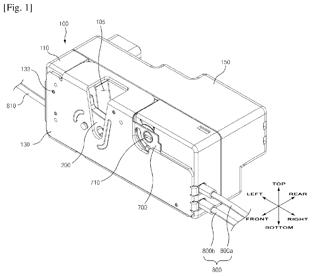
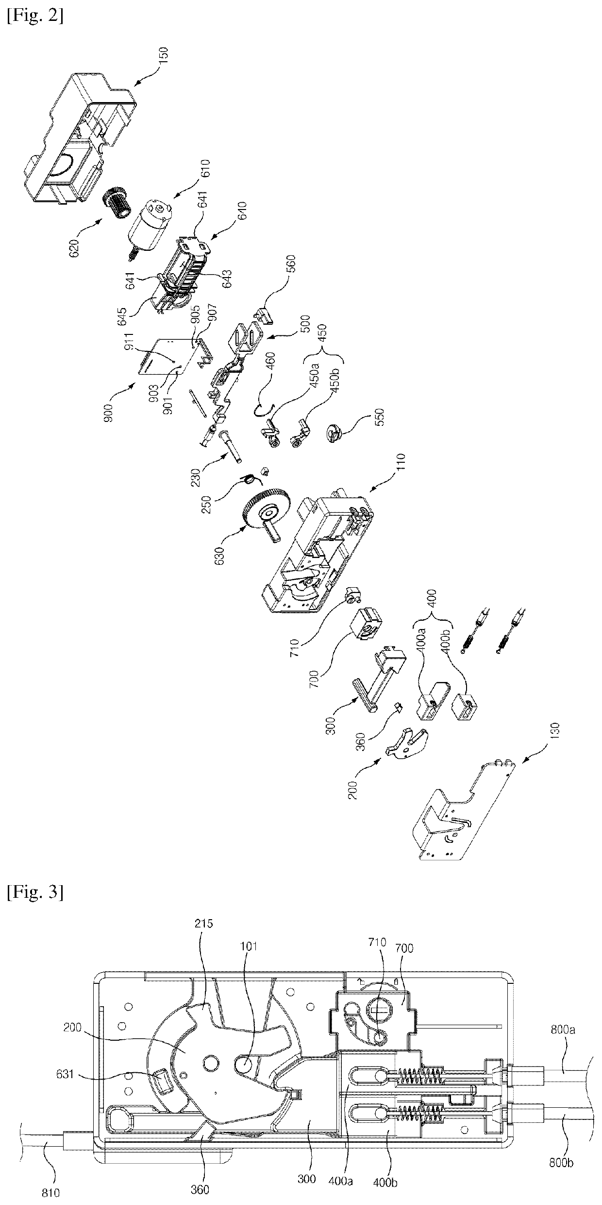
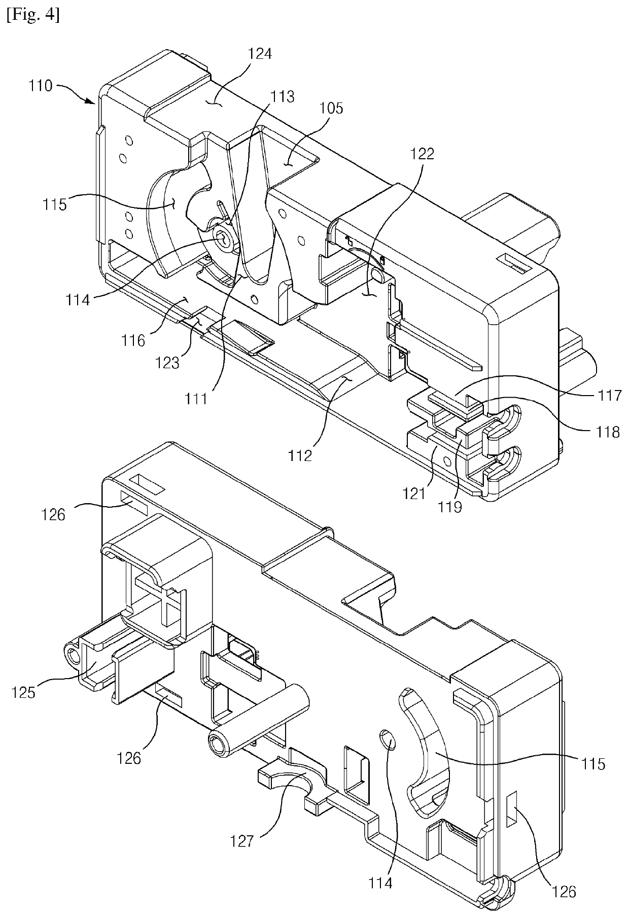
[0174]As illustrated in FIGS. 1 to 33, the door latch system according to the first exemplary embodiment of the present invention includes: a housing 100; a latch 200 pivotally and rotatably installed in the housing 100; a main locking member 300 slidingly installed in the housing 100 for locking the latch 200; a sub-locking member 400 slidingly installed in the housing 100 and disposed in one side of the main locking member 300; and a connecting means which enables simultaneous sliding of the main locking member 300 and the sub-locking member 400, or sliding of only the sub-locking member 400.
[0175]As illustrated in FIGS. 1 to 13, the housing 100 includes: a first housing 110, a second housing 130 disposed in front of the first housing 110, and the third housing 150 disposed in the backside of the first housing 110.
[0176]As illustrated in FIG. 1, in the housing 100, the front means the direction towards the second housing 130, and the backside means direction towards the third hous...
embodiment 2
[0465]In describing the door latch system according to the second exemplary embodiment of the present invention, same symbols will be used for the same or the similar elements as those of the door latch system according to the first exemplary embodiment of the present invention, and the detailed description and illustration will be omitted.
[0466]As illustrated in FIGS. 34 to 40, the door latch system according to the second exemplary embodiment of the present invention further includes a rotating member 370 for sliding the main locking member 300′ by the latch 200.
[0467]Since only the body 310′ of the main locking member 300′ is formed in a different form than that of the first exemplary embodiment of the present invention, only the body 310′ will be described and the description about the other identical configurations will be omitted.
[0468]The body 310′ constitutes the right portion of the main locking member 300′.
[0469]The body 310′ comprises the first step portion 311′ and the s...
embodiment 3
[0513]As illustrated in FIGS. 41 to 72, the door latch system according to the first exemplary embodiment of the present invention is characterized in that and includes: a housing 4100; a latch 4200 pivotally and rotatably installed in the housing 4100; a main locking member 4300 slidingly installed in the housing 4100 for locking the latch 4200; and a driving unit 4600 for pivotally rotating the latch 4200, wherein the driving unit 4600 comprises a main gear 4630, and a geared portion 4632 wherein gear teeth are formed in a portion of the peripheral surface of the main gear 4630 and a non-geared portion 4643 (without gear teeth) is formed in the remaining portion of the peripheral surface thereof.
[0514]As illustrated in FIGS. 41 to 44, the housing 4100 includes a first housing 4110, a second housing 4130 disposed in front of the first housing 4100, and the third housing 4150 disposed in the backside of the first housing 4100.
[0515]A striker insertion slot 4105 is formed in the uppe...
PUM
 Abstract
Description
Claims
Application Information
 - R&D
- Intellectual Property
- Life Sciences
- Materials
- Tech Scout
- Unparalleled Data Quality
- Higher Quality Content
- 60% Fewer Hallucinations
Browse by: Latest US Patents, China's latest patents, Technical Efficacy Thesaurus, Application Domain, Technology Topic, Popular Technical Reports.
© 2025 PatSnap. All rights reserved.Legal|Privacy policy|Modern Slavery Act Transparency Statement|Sitemap|About US| Contact US: help@patsnap.com


