Method for density compensation by drop size adaptation

a density compensation and drop size technology, applied in the field of density compensation by drop size adaptation, can solve the problem that the modification of color density values will amount to compensating, and achieve the effect of quick and flexible correction of color density fluctuations

Active Publication Date: 2020-03-24
HEIDELBERGER DRUCKMASCHINEN AG
View PDF11 Cites 0 Cited by
  • Summary
  • Abstract
  • Description
  • Claims
  • Application Information

AI Technical Summary

Benefits of technology

[0006]It is accordingly an object of the invention to provide a method for modifying color density values in a dot-based printing system with a control unit, which overcomes the herein afore-mentioned disadvantages of the heretofore-known methods of this general type and in which color density fluctuations may be corrected in a quick and flexible way.
[0007]With the foregoing and other objects in view there is provided, in accordance with the invention, a method for modifying color density values in a dot-based printing system with a control unit, which is particularly suitable for modifying color density values in inkjet printing machines. However, it may also be used in other dot-based printing systems. The method of the invention relies on the use of a control unit that is supplied with a digital original. Furthermore, the control unit is supplied with desired modifications of color density values in the print image. These modifications may be intended modifications of color density values defined by an operator. In general, however, the modification of color density values will amount to compensating for undesired color density value fluctuations caused by the construction of the printing system to avoid brightness differences in the printed image. The invention envisages that the color density values are modified after a raster image has been created (after a printing image has been scanned) and that the number and size of the print dots to be applied to the printing material are modified in order to achieve pre-defined color density values. Since the color density values are modified after the creation of the raster image, the color density value correction process does without the time-consuming, slow process of creating the raster image. Thus, in accordance with the present invention, the image data of the raster images of the individual color separations are used in the control unit and no additional raster image needs to be created. The invention further envisages that based on the available raster values, the number or size of the print dots to be applied to the printing material are modified. A modification of the number or size of the print dots to be applied to the printing material results in a modification of the color density and thus a modification of the brightness on the printing material. Thus, undesired color density fluctuations in particular may be easily and quickly corrected, eliminating brightness differences in the printed image in a direction perpendicular to the printing direction. This allows the use of print heads that emit drops of different volumes for manufacturing reasons. Eliminating the need for a new raster image means that the printing process is greatly accelerated, causing inkjet printers to become more widely accepted in the market because the machines available on the market today require very long set-up and correction times prior to the printing process.
[0012]It is advantageously also envisaged that the control unit is supplied with the image data of an image inspection system that scans printing materials that have been produced in the dot-based printing system. The image inspection system may be disposed in the printing system itself or outside the printing system as an external device. Printing materials are removed from the printing system and inspected or are inspected directly inside the printing system by the image inspection system at regular intervals and in particular during the start-up phase. The actual color values that have been obtained in this way are fed to the control unit, which compares them to the target color values of the digital original. If color density deviations occur, correction signals that correspond to compensation values are forwarded to the print head actuation electronics cards, which manipulate the drops to be emitted in terms of their size and number to compensate for the detected color density deviations. It is to be understood that during the entire printing process, a printing material that has been produced in the printing system may be scanned at any time for the purpose of continuous quality control and the correction process may be repeated. In this way, a closed control loop may be created and density deviations that have been detected by the image inspection system may be automatically compensated for during an ongoing print job. This makes the operator's job much easier because the quality of the print in terms of color density is automatically optimized.
[0013]In yet another embodiment of the invention it is envisaged that to minimize quantization noise, a correction function, in particular sigma delta modulation, is used for the modification of the color density values of the print dots to be applied to the printing material. The image data on the print head actuation electronics cards have a very low screen resolution because the drop size may vary only between the four options zero, S, M, and L. This very low resolution results in much quantization noise. In order to minimize noise density within the useful frequency spectrum of the image data, the invention proposes the use of a correction function. This function suppresses the noise. The preferred function to be used is sigma-delta modulation, i.e. the modification of the image data is sigma-delta modulation. This means that a constant percentaged density modification is attained in that for every pixel in the image data, the heretofore existing deviation from the color density target value is measured and when a threshold is reached, a pixel value is discreetly modified in the right direction (plus or minus) to minimize the deviation error.

Problems solved by technology

In general, however, the modification of color density values will amount to compensating for undesired color density value fluctuations caused by the construction of the printing system to avoid brightness differences in the printed image.

Method used


Image

  • Method for density compensation by drop size adaptation

Examples


Embodiment Construction

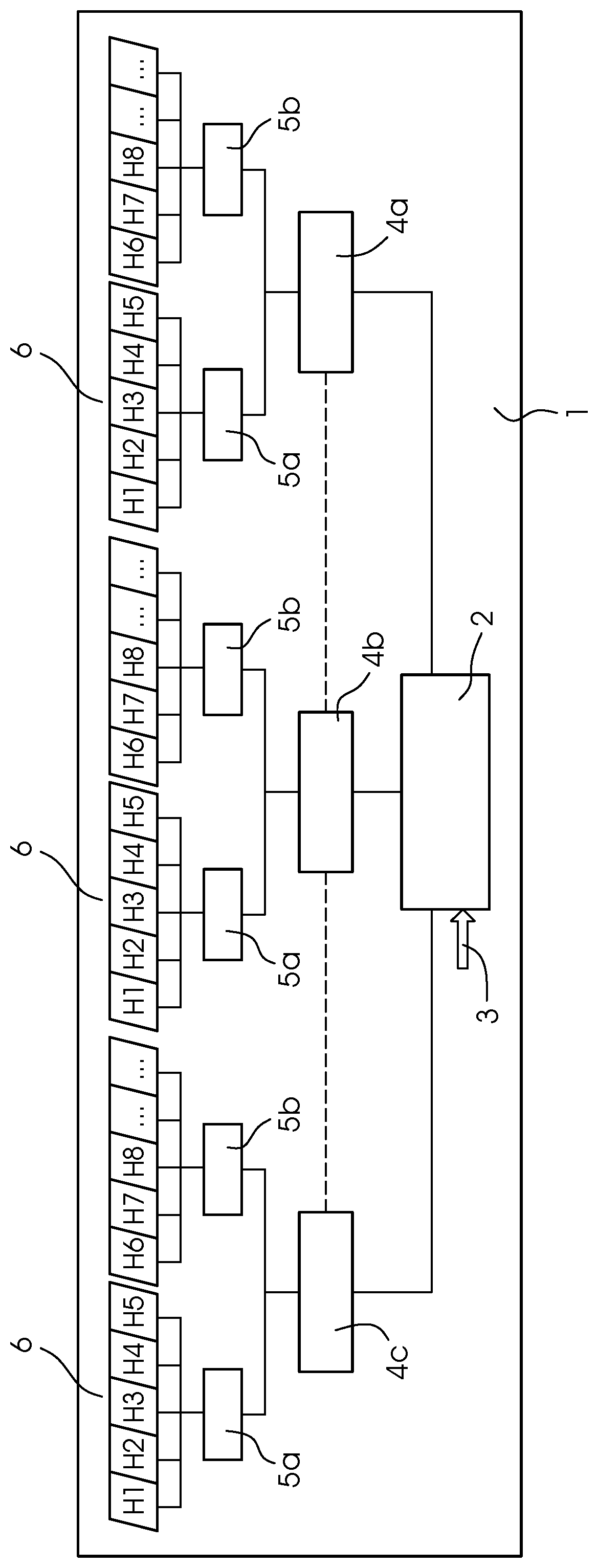
[0019]Referring now in detail to the single figure of the drawing, there is seen an inkjet printing machine 1 using a page-width printing bar. In the present example, the printing bar has three print heads 6 containing printing nozzles. In the figure, every print head 6 has ten printing nozzles and every print head 6 applies a single color to the printing material. Every print head 6 is actuated by two print head actuation electronics cards in the form of inkjet converter cards 5a, 5b. It is the job of the inkjet converter cards 5a, 5b to convert switch-on time signals of the individual nozzles into control signals for actuating the print heads 6. For reasons of computing capacity, two inkjet converter cards 5a, 5b are provided for every print head 6 in the figure.

[0020]The printing system 1 additionally has digital graphics cards 4a, 4b, 4c, with one digital graphics card controlling one color channel. The digital graphics cards 4a, 4b, 4c convert a screened halftone image of a col...


PUM

PropertyMeasurementUnit
volumeaaaaaaaaaa
volumeaaaaaaaaaa
volumeaaaaaaaaaa

Abstract

A method for modifying color density values in a dot-based printing system uses a control unit. The control unit implements the modification of the color density values after a raster image has been created and modifies the number and / or size of print dots to be applied to a printing substrate in order to attain pre-defined color density target values.

Description

CROSS-REFERENCE TO RELATED APPLICATION[0001]This application claims the priority, under 35 U.S.C. § 119, of German Patent Application DE 10 2016 201 245.2, filed Jan. 28, 2016; the prior application is herewith incorporated by reference in its entirety.BACKGROUND OF THE INVENTIONField of the Invention[0002]The present invention relates to a method for modifying color density values in a dot-based printing system using a control unit.[0003]In printing machines and printers using inkjet technology in particular, color density fluctuations occur again and again, causing brightness differences on the printing substrates in a direction perpendicular to the printing direction. Those density fluctuations are caused by the fact that for manufacturing reasons, the nozzles in the print heads frequently emit drops of different volumes. In accordance with the prior art, that density fluctuation problem is corrected by an image correction before a raster image of the different color separations ...

Claims


Application Information

Patent Timeline
Patent Type & Authority Patents(United States)
IPC IPC(8): B41J2/045H04N1/58G06K15/02H04N1/405B41J2/205B41J2/21H04N1/52B41J29/393
CPCB41J2/04581B41J2/04595B41J2/2054G06K15/1836B41J2/2146H04N1/4055H04N1/58H04N1/52B41J2/04508B41J2/04558B41J2/04593B41J29/393B41J2029/3935G06K2215/101G06K2215/0094
Inventor TRACHANAS, ILIASJUNGHANS, GERD
Owner HEIDELBERGER DRUCKMASCHINEN AG
Why Eureka
Try Eureka