Method for density compensation by drop size adaptation

Active Publication Date: 2017-08-03
HEIDELBERGER DRUCKMASHINEN AG
View PDF3 Cites 3 Cited by
  • Summary
  • Abstract
  • Description
  • Claims
  • Application Information

AI Technical Summary

Benefits of technology

[0006]It is accordingly an object of the invention to provide a method for modifying color density values in a dot-based printing system with a control unit, which overcomes th

Problems solved by technology

In general, however, the modification of color density values will amount to compensating for undesired color density va

Method used


Image

  • Method for density compensation by drop size adaptation
  • Method for density compensation by drop size adaptation

Examples


Embodiment Construction

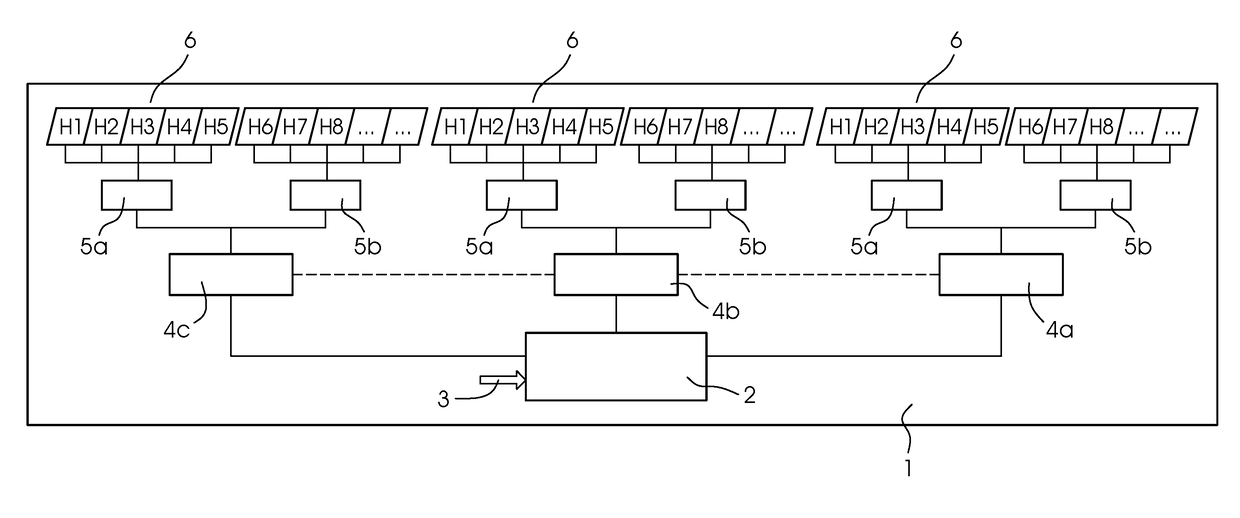
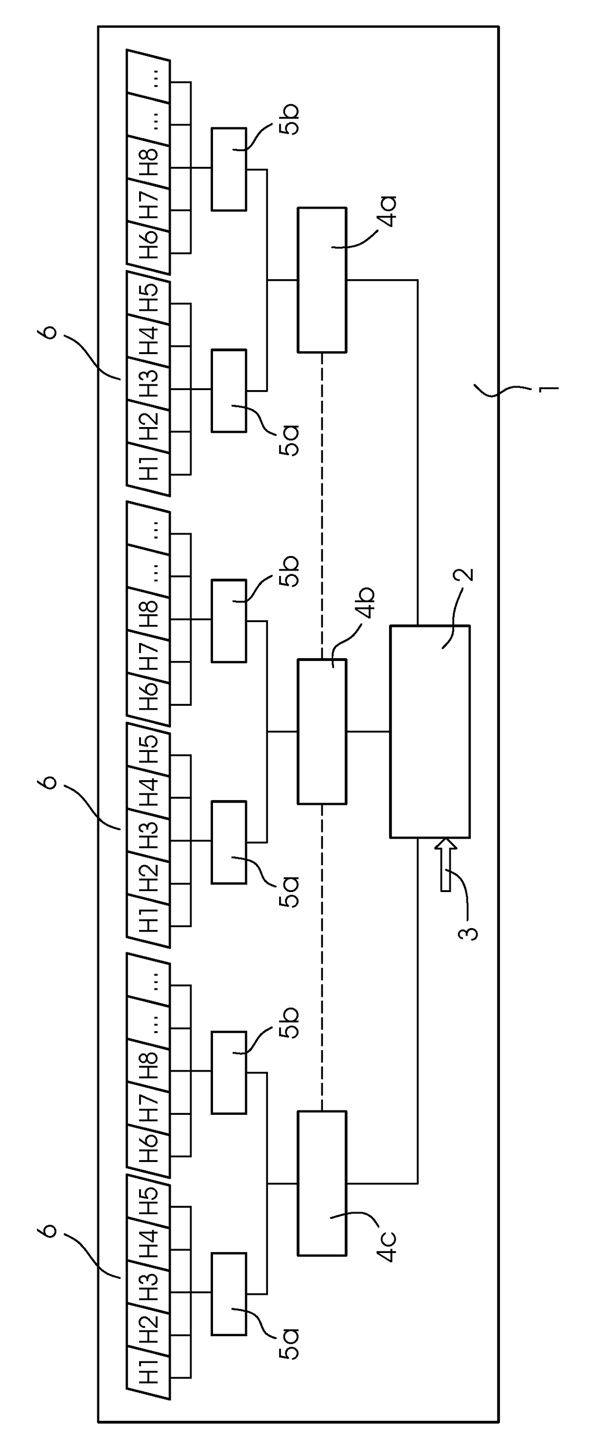
[0019]Referring now in detail to the single figure of the drawing, there is seen an inkjet printing machine 1 using a page-width printing bar. In the present example, the printing bar has three print heads 6 containing printing nozzles. In the figure, every print head 6 has ten printing nozzles and every print head 6 applies a single color to the printing material. Every print head 6 is actuated by two print head actuation electronics cards in the form of inkjet converter cards 5a, 5b. It is the job of the inkjet converter cards 5a, 5b to convert switch-on time signals of the individual nozzles into control signals for actuating the print heads 6. For reasons of computing capacity, two inkjet converter cards 5a, 5b are provided for every print head 6 in the figure.

[0020]The printing system 1 additionally has digital graphics cards 4a, 4b, 4c, with one digital graphics card controlling one color channel. The digital graphics cards 4a, 4b, 4c convert a screened halftone image of a col...


PUM


Abstract

A method for modifying color density values in a dot-based printing system uses a control unit. The control unit implements the modification of the color density values after a raster image has been created and modifies the number and/or size of print dots to be applied to a printing substrate in order to attain pre-defined color density target values.

Description

CROSS-REFERENCE TO RELATED APPLICATION[0001]This application claims the priority, under 35 U.S.C. §119, of German Patent Application DE 10 2016 201 245.2, filed Jan. 28, 2016; the prior application is herewith incorporated by reference in its entirety.BACKGROUND OF THE INVENTIONField of the Invention[0002]The present invention relates to a method for modifying color density values in a dot-based printing system using a control unit.[0003]In printing machines and printers using inkjet technology in particular, color density fluctuations occur again and again, causing brightness differences on the printing substrates in a direction perpendicular to the printing direction. Those density fluctuations are caused by the fact that for manufacturing reasons, the nozzles in the print heads frequently emit drops of different volumes. In accordance with the prior art, that density fluctuation problem is corrected by an image correction before a raster image of the different color separations i...

Claims


Application Information

Patent Timeline
IPC IPC(8): B41J2/045H04N1/405G06K15/02B41J29/393
CPCB41J2/04558B41J2/04593B41J2/04595B41J29/393G06K2215/0094G06K15/1836B41J2029/3935G06K2215/101H04N1/4055B41J2/2054B41J2/2146B41J2/04508B41J2/04581H04N1/52H04N1/58
Inventor TRACHANAS, ILIASJUNGHANS, GERD
Owner HEIDELBERGER DRUCKMASHINEN AG
Why Eureka
Try Eureka