Self-propelled cleaning device
- Summary
- Abstract
- Description
- Claims
- Application Information
AI Technical Summary
Benefits of technology
Problems solved by technology
Method used
Image

Examples
first embodiment
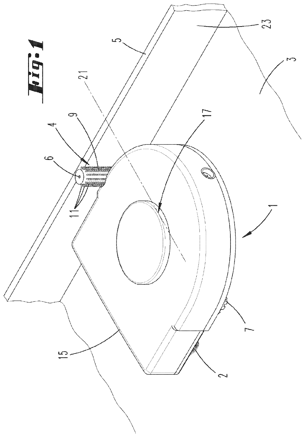
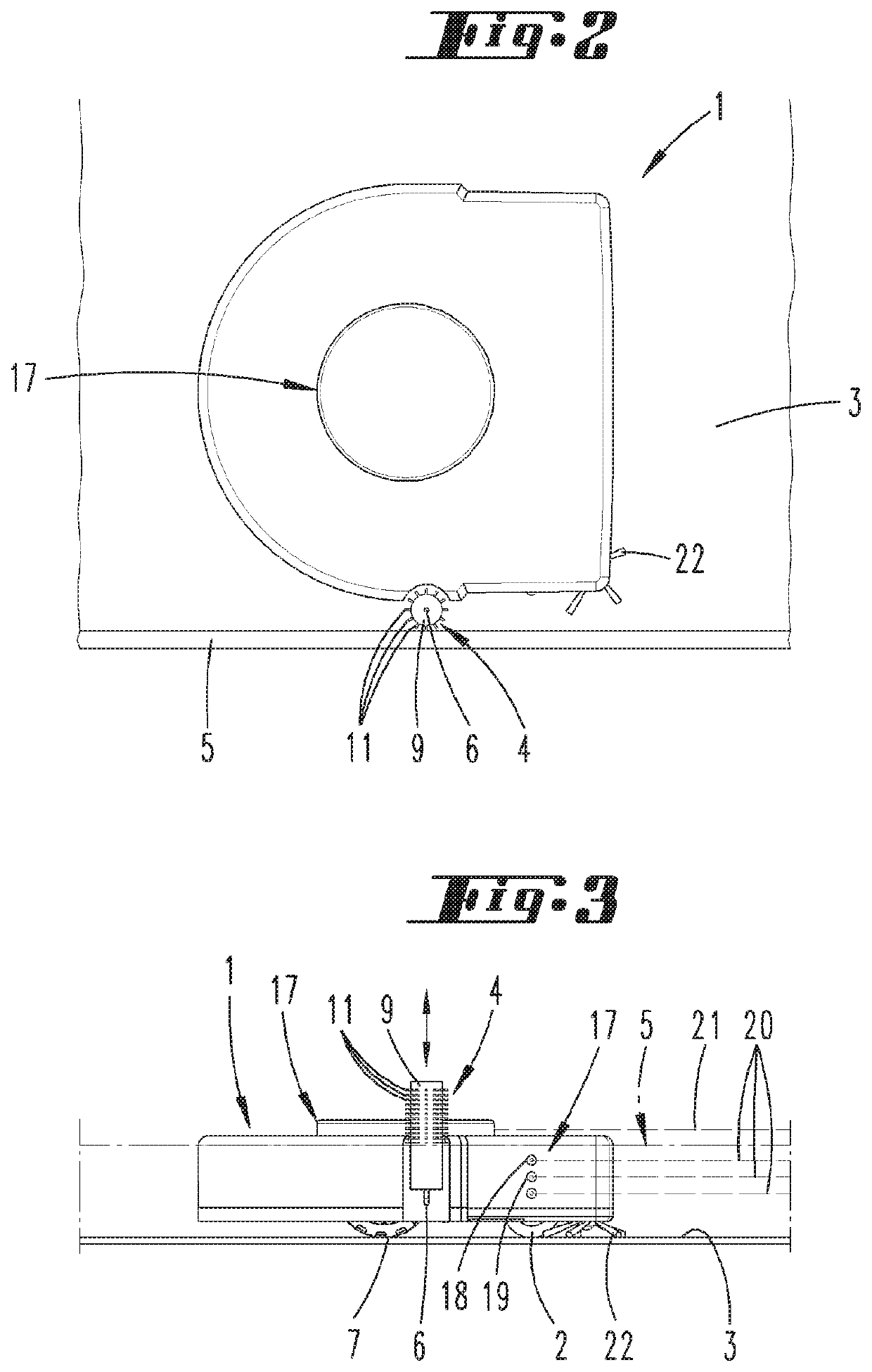
[0041]FIGS. 1 to 3 show a cleaning device 1 according to a For example, the cleaning device 1 is here designed as an autonomous robotic vacuum. The cleaning device 1 has a housing 15, a surface cleaning device 2 and traversing wheels, which provide a standing surface 7 that contacts a partial area of a surface 3. The surface cleaning system 2 has a bristle roller and a motor-fan unit (not shown). An above-floor cleaning element 4 is laterally arranged on the housing 15 relative to a usual forward traveling direction of the cleaning device 1, and serves to clean an above-floor surface 5. For example, the above-floor surface 5 is here a plateau of a baseboard. The baseboard further has a lateral surface 23, which rises perpendicularly from the surface 3.
[0042]The above-floor cleaning element 4 is here designed as a cylindrical roller 9, which has a plurality of bristles 11 that point radially outward. The above-floor cleaning element 4 is mounted on a rotational axis 6 and can rotate...
second embodiment
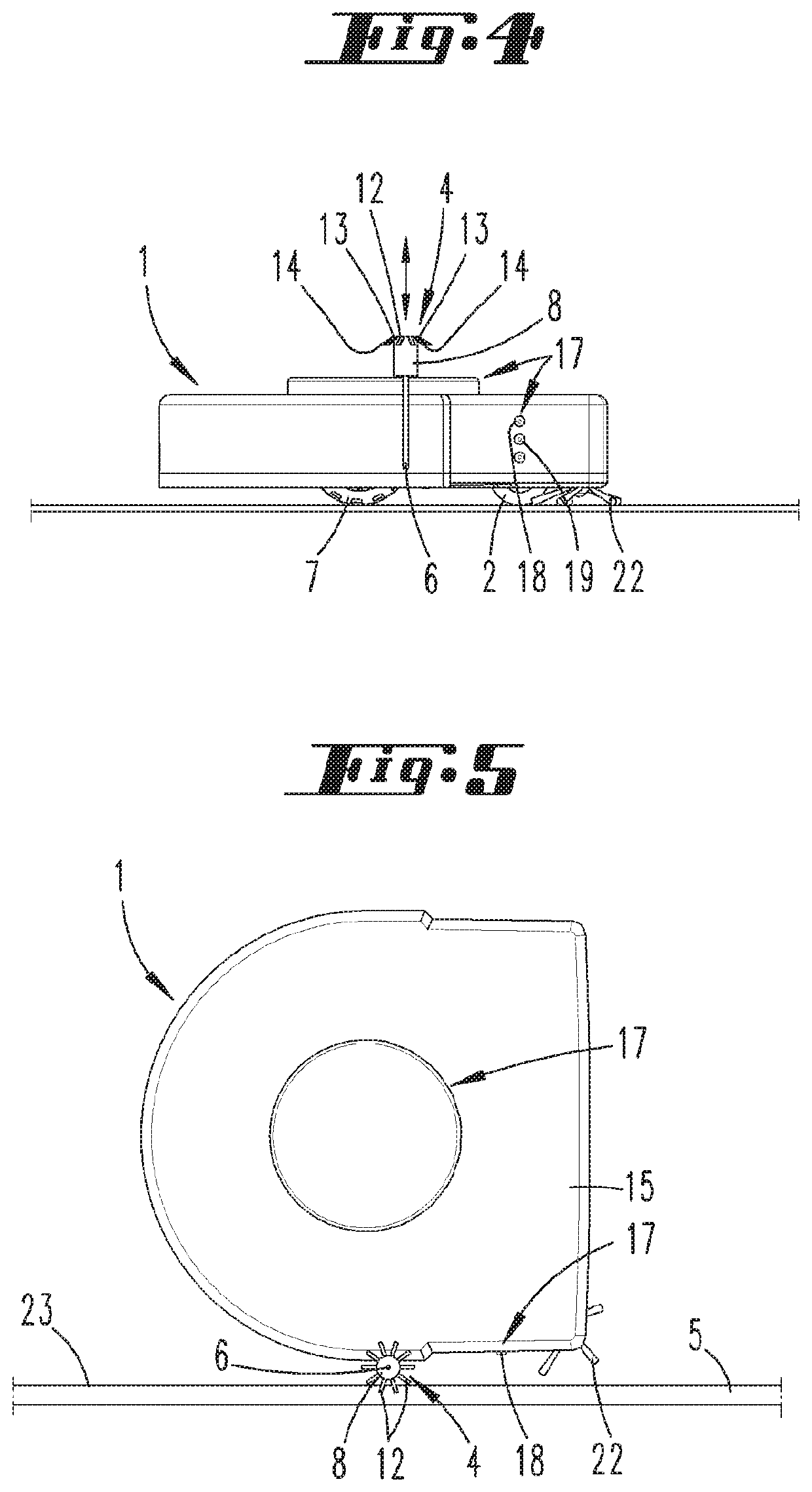
[0050]FIGS. 4 and 5 show a cleaning device 1, in which the above-floor cleaning element 4 is a body that can also rotate around a vertical rotational axis 6. This above-floor cleaning element 4 is designed as a brush 8 with a plurality of textile filaments 12, which each are anchored on a fastening location 13 in the brush 8, and the force of gravity causes their opposing free end areas 14 to hang down.
[0051]The brush 8 rotates while an above-floor surface 5 is being cleaned, so that the filaments 12 are lifted in response to the centrifugal force, and brush over the above-floor surface 5. In addition, a wetting system (not shown) can be allocated to the above-floor cleaning element 4, and ensures that the filaments 12 are wetted. Alternatively, the filaments 12 can also be manually wetted by a user.
[0052]Otherwise, the procedure for this cleaning device 1 can take place analogously to the exemplary embodiment described above, i.e., the above-floor cleaning element 4 can also be shi...
third embodiment
[0053]FIGS. 6 to 8 show the invention, in which the above-floor cleaning element 4 has a comb 10 with bristles 11 arranged vertically one over the other. The comb 10 can be pivoted relative to the housing 15 around a rotational axis 6. The comb 10 can here be shifted from a resting position pivoted into the housing 15 into an above-floor cleaning position pivoted out of the housing 15. Shifting preferably takes place automatically upon detection of an above-floor surface 5. FIG. 8 shows the above-floor cleaning element 4 in a state pivoted positively into the housing 15.
[0054]FIG. 9 presents an alternative embodiment thereto, in which the above-floor cleaning element 4 can be shifted proceeding from the described resting position linearly out of the housing 15, so as to perform an above-floor cleaning operation. For example, the above-floor cleaning element 4 designed as a comb 10 can be pivoted around the rotational axis 6 while cleaning an above-floor surface 5, for example in a b...
PUM
 Abstract
Description
Claims
Application Information
 - R&D
- Intellectual Property
- Life Sciences
- Materials
- Tech Scout
- Unparalleled Data Quality
- Higher Quality Content
- 60% Fewer Hallucinations
Browse by: Latest US Patents, China's latest patents, Technical Efficacy Thesaurus, Application Domain, Technology Topic, Popular Technical Reports.
© 2025 PatSnap. All rights reserved.Legal|Privacy policy|Modern Slavery Act Transparency Statement|Sitemap|About US| Contact US: help@patsnap.com