Tubular electrical machines

a technology of electrical machines and tubular bodies, which is applied in the direction of electrical apparatus, dynamo-electric machines, sea energy generation, etc., can solve the problems of tubular electrical machines having the physical size, the need to control the eddy current in the core of the stator, and the control of the eddy curren

Inactive Publication Date: 2007-11-01
LEFLEM GRAHAM DEREK
View PDF5 Cites 1 Cited by
  • Summary
  • Abstract
  • Description
  • Claims
  • Application Information

AI Technical Summary

Benefits of technology

[0009] The tubular construction of the stator offers several advantages over a linear construction. First of all, the resulting stator has inherent mechanical strength and rigidity arising from its tubular shape so that it can better withstand the forces that act on it when the tubular electrical machine is operating. The length of the stator for a tubular electrical machine can also be much less than the flat stator for a linear electrical machine of equivalent rating. This is because the coils of the stator winding of a tubular electrical machine are annular and there are no endwindings. More particularly, the tubular construction means that the effective length of the stator winding is longer (being approximately the inner diameter of the stator core multiplied by π) so the axial length of the stator can be substantially reduced while still providing the same air gap area as the linear electrical machine.
[0016] The casing may have a good thermal conductivity so that the stator can be cooled by conduction of heat out through the casing. In one practical embodiment where the present invention is used as a direct drive generator for a wave energy machine, the casing can be surrounded by sea water so that the heat generated in the stator core and windings can be conducted directly out through the casing to the sea water, which acts as an infinite heat sink.
[0022] Each coil of the stator winding is preferably inserted into an associated one of the axially-spaced slots as the axially successive layers of laminations are formed. The coils are preferably of a simple circular section with two spiral wound tiers mounted side by side in the annular slots. One tier is wound in one rotation and the other tier is wound with the opposite rotation, so that when they are placed side by side and connected together they will both carry current in the same direction. The coils are therefore simple to make and assemble. The number of axially-spaced slots in the substantially cylindrical surface of the stator will depend on the pole number of the tubular electrical machine and the number of coils per pole.
[0024] Clamp plates can be placed at both ends of the assembled stator to compress the successive layers of stacked laminations between the clamp plates and provide a rigid support for the mechanical loads. The clamped stator is then preferably placed in a sealed tank where it undergoes a Vacuum Pressure Impregnation (VPI) process. More particularly, the stator is subjected to a vacuum before resin is pumped into the assembly. The stator is then cured at an elevated temperature (typically about 180° C.) for a period of time to set the resin. After the VPI process has been carried out, the stator is essentially an integral structure with the successive layers of circumferentially-stacked laminations bonded together and insulated by the cured resin. The stator therefore has a high degree of structural rigidity and is able to withstand the mechanical forces that it experiences during the normal operation of the tubular electrical machine.
[0027] The thickness of the laminations in the circumferential direction should be chosen such that any heat generated in the radially inner regions of the stator core can be easily conducted straight out to the protective casing or outer housing mentioned above.

Problems solved by technology

However, a main drawback and limitation of their use in large physical sizes is the need to control eddy currents in the core of the stator.
The inability to control eddy currents has so far prevented the development of tubular electrical machines having the physical size and rating that would enable them to be used as a direct drive generator for large-scale wave energy machines.
The magnetic permeability and thermal conductivity of such amorphous stator cores are poor compared to the conventional laminations used in the flat stators of linear electrical machines and they can only be produced in small physical sizes.
Although the laminations are mounted in the correct plane to reduce eddy currents, the proposed solution makes construction of the stator very difficult because of the need for the lamination groups and the wedges to be mechanically connected together.
However, this leads to very high magnetising requirements and is simply not economical for most practical purposes.

Method used


Image

  • Tubular electrical machines
  • Tubular electrical machines
  • Tubular electrical machines

Examples


Embodiment Construction

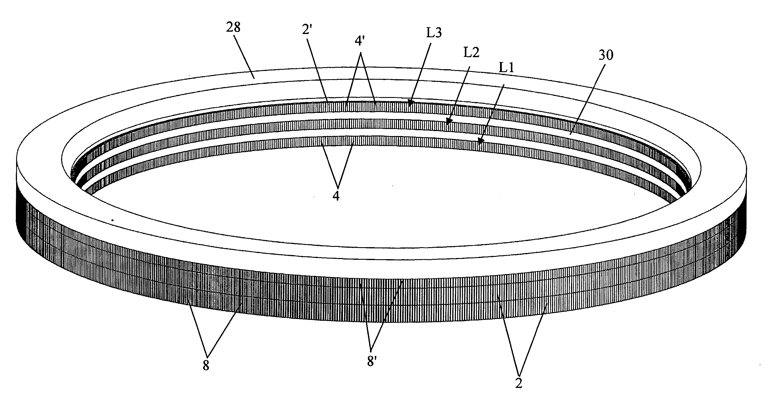
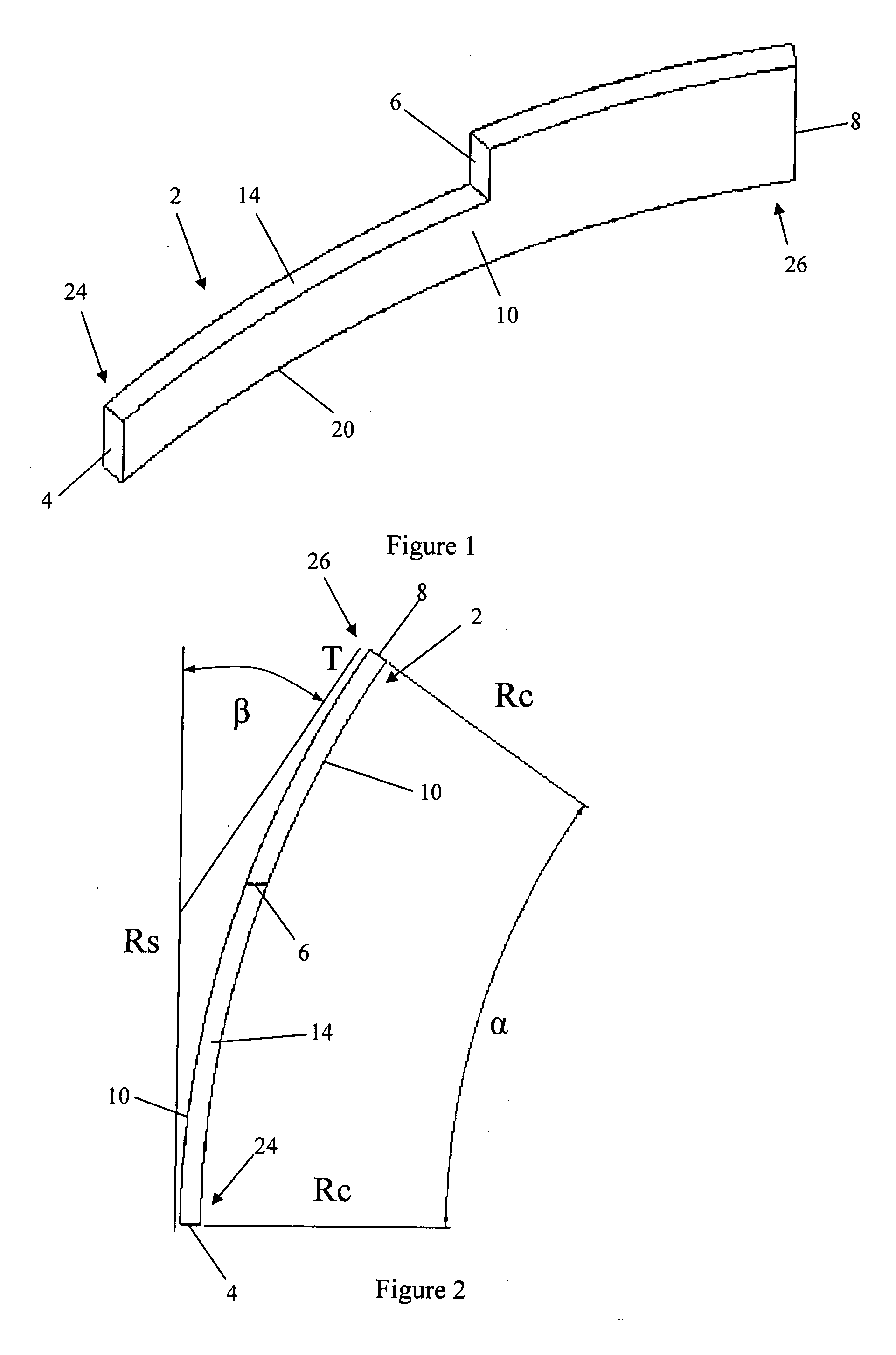
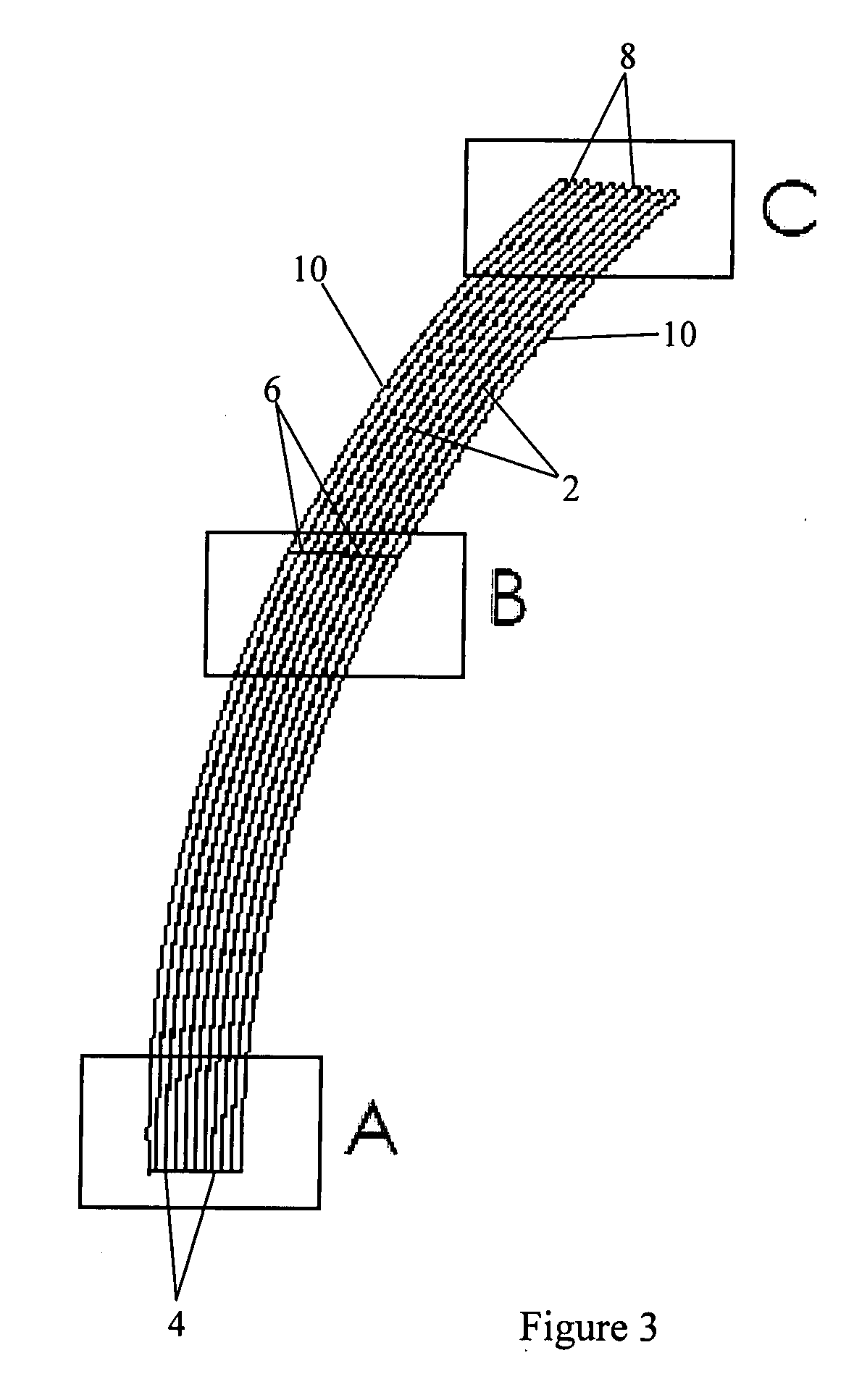
[0038] With reference to FIGS. 1 and 2 a lamination 2 for forming a stator of a tubular electrical machine is punched out of a blank of electrical steel and then mechanically pressed to adopt a curved shape. The thickness of the electrical steel can be the maximum available in conventional electrical steels (currently about 1 mm) but thinner or thicker steels can be used. The laminations can be pre-insulated or coated with a thin film of insulating material after forming. The lamination 2 has an L-shaped or stepped configuration and includes a first radially inner edge 4 that forms part of the cylindrical inner surface of the stator, a second radially inner edge 6 that forms part of a cylindrical end surface of a slot for receiving a coil C of a stator winding (FIG. 6 to 8) and a radially outer edge 8 that forms part of the outer surface of the stator. The lamination 2 is curved to extend along an arc of a circle of predetermined diameter. The degree of arc a along which the laminat...


PUM


Abstract

The present invention provides a stator for a tubular electrical machine having a substantially cylindrical inner surface containing a series of axially-spaced slots for receiving the coils of a stator winding. The stator comprises axially successive layers of laminations 2, each layer being formed from a number of curved laminations stacked together in the circumferential direction.

Description

FIELD OF THE INVENTION [0001] The present invention relates to tubular electrical machines, and in particular to physically large tubular electrical motors and generators that are suitable for use as direct drive generators for converting wave energy into electrical power. BACKGROUND OF THE INVENTION [0002] It is known to use linear electrical machines as generators to convert the reciprocating movement captured by a wave energy machine into electrical power. [0003] Tubular electrical machines are similar to linear electrical machines but instead of having a flat stator they have a tubular stator where the slots for receiving the coils of the stator winding are formed in the cylindrical inner surface. The flat translator is replaced with a hollow or solid tubular translator, which in one embodiment has rows of permanent magnets mounted around its cylindrical outer surface. In another embodiment, the translator has solid coils mounted in slots in a similar manner to the stator so tha...

Claims


Application Information

Patent Timeline
Patent Type & Authority Applications(United States)
IPC IPC(8): H02K41/00H02K35/00
CPCH02K1/145Y02E10/38H02K1/16Y02E10/30H02K1/12H02K7/1876
Inventor LEFLEM, GRAHAM DEREK
Owner LEFLEM GRAHAM DEREK
Why Eureka
Try Eureka