Ultrasonic anemometer and method for determination of at least one component of a wind velocity vector or the velocity of sound in the atmosphere

Active Publication Date: 2020-04-14
METEK METEOROLOGISCHE MESSTECHN
View PDF22 Cites 4 Cited by
  • Summary
  • Abstract
  • Description
  • Claims
  • Application Information

AI Technical Summary

Benefits of technology

[0032]Therefore, in the anemometer designed according to the invention, the two remaining sections are not horizontally oriented, but inclined. In this manner, the known restrictions from section shadowing with the known wind measuring devices with one vertical and two horizontal measuring sections is avoided.
[0033]From the wide beam characteri

Problems solved by technology

A substantial disadvantage of this arrangement is the horizontal orientation of the other measuring sections.
Hereby, the usable wind direction area is limited, since sectors with an inflow direction almost or completely in parallel with the section have a high shadowing error and result in a respectively lower quality of the measured horizontal wind components.
Though the vertical section enables high measuring accuracy of the vertical wind component, one disadvantage of this section orientation is wetting of the lower sensor by rain or dew or, in case of heated sensor heads, by melt water.
Therefore, the membranes of the vertical measuring section are oriented horizo

Method used


Image

  • Ultrasonic anemometer and method for determination of at least one component of a wind velocity vector or the velocity of sound in the atmosphere
  • Ultrasonic anemometer and method for determination of at least one component of a wind velocity vector or the velocity of sound in the atmosphere
  • Ultrasonic anemometer and method for determination of at least one component of a wind velocity vector or the velocity of sound in the atmosphere

Examples


Example

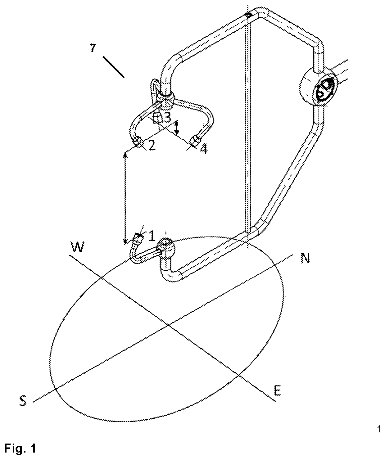
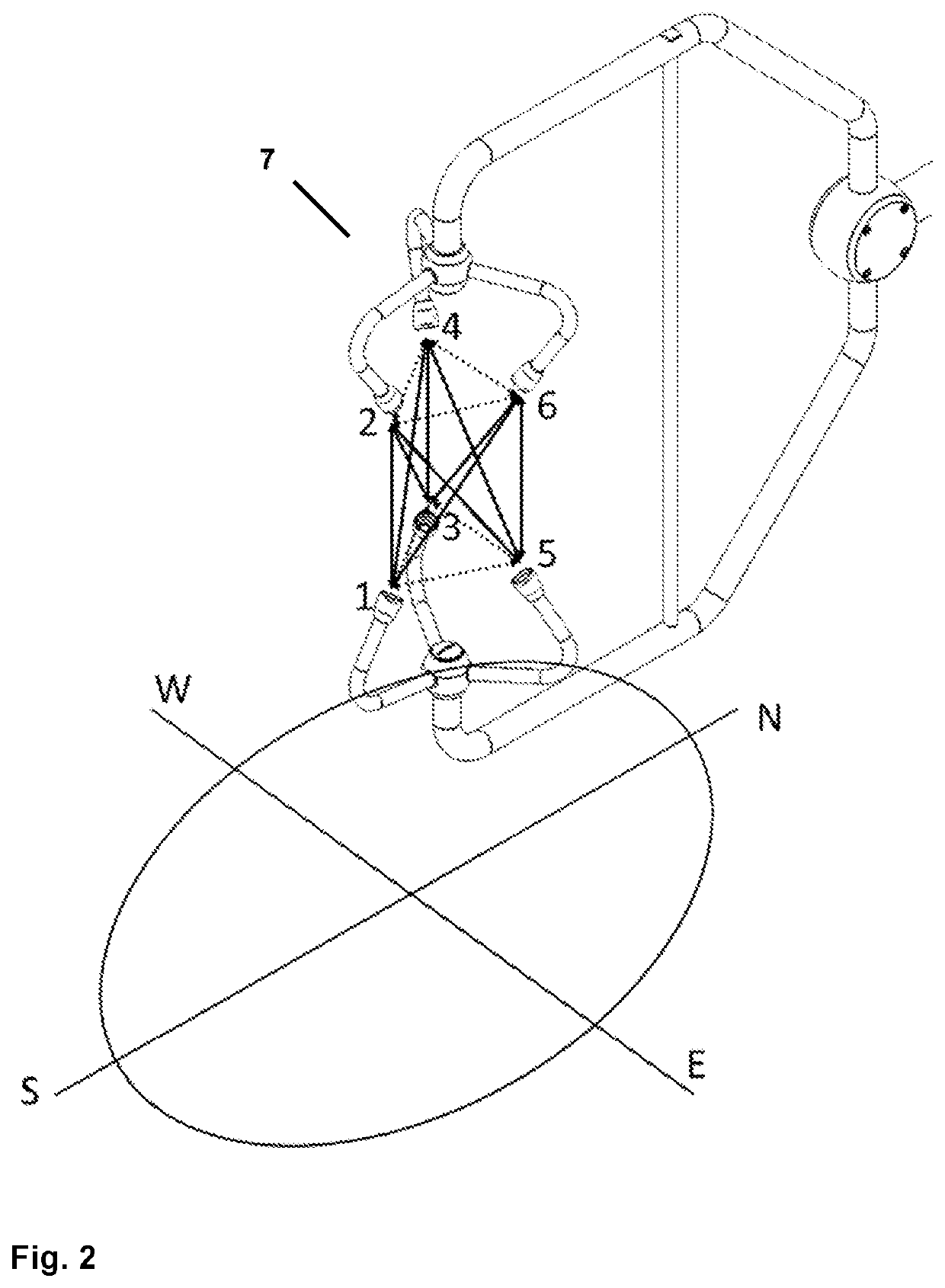
[0039]FIG. 1 shows an ultrasonic wind measuring device 7, in which the lower sound transducer 2 of the vertical measuring section is simultaneously used for measuring two inclined wind components. The sound transducers 1 and 2 spread out the vertical measuring section 1-2, and with the sound transducers 1 and 3 or 1 and 4, resp., the inclined measuring sections 1-3 and 1-4 are realized. The actual section angles and section lengths can deviate from this example.

[0040]According to a particularly advantageous structural further development of the embodiment according to FIG. 1, it is conceivable to additionally offset the sound transducer 2 upward and the sound transducers 3 and 4 downward. With this offset, possible shadowing by the sound transducer 2 on the sections 1-3 as well as 1-4 is avoided or at least reduced, also with inclined inflow directions.

[0041]The transit times of the sound waves recorded on the measuring sections are transmitted to an evaluation unit, in which, on th...


PUM


Abstract

An ultrasonic anemometer (7) as well as a method for determination of at least one component of a wind velocity vector and/or a velocity of sound includes at least one sound transducer at least temporarily working as a transmitter (1, 2, 3, 4, 5, 6, 15, 16) with a sound emission surface for emitting sound waves and at least one sound transducer at least temporarily working as a receiver (1, 2, 3, 4, 5, 6, 15, 16) with a sound detection surface for at least partially receiving the emitted sound waves. An evaluation unit, determines at least one component of a wind velocity vector and/or the velocity of sound, based on a recorded transit time, which the sound waves require on a measuring section located between the sound emission surface of the at least one transmittor and the sound detection surface of the at least one receiver to cover the distance of this measuring section. At least one measuring section is provided between a first sound emission surface of a first transmitter and a first sound detection surface of a first receiver arranged approximately vertical to the earth's surface and the first sound emission surface and/or the first sound detection surface is inclined compared to the horizontal.

Description

[0001]The instant application should be granted the priority dates of Apr. 12, 2015, the filing date of German Patent Application DE 10 2015 004 408.7, Oct. 19, 2015, the filing date of German Patent Application DE 10 2015 013 399.3, and Apr. 12, 2016, the filing date of the corresponding International patent application PCT / EP2016 / 025034.BACKGROUND OF THE INVENTION[0002]The invention relates to an ultrasonic anemometer for measurement of the velocity of inflowing wind with at least one transmitter for emitting sound waves and at least one receiver for at least partially receiving the emitted sound waves, and with an evaluation unit, which, taking a recorded transit time of the sound waves on a measuring section located between transmitter and receiver as the basis, determines the quantity of at least one component of the wind vector and / or the velocity of sound.[0003]Different measuring instruments are known, using which the local measurement of the velocity of a flow field, in par...

Claims


Application Information

Patent Timeline
IPC IPC(8): G01P5/08G01P5/18G01P13/02G01F1/66G01P5/24
CPCG01P13/02G01F1/667G01P5/18G01P5/245G01P5/08
Inventor PETERS, GERHARD
Owner METEK METEOROLOGISCHE MESSTECHN
Why Eureka
Try Eureka