Supercharge Your Innovation With Domain-Expert AI Agents!

Locking structure of switch device

a technology of locking structure and switch device, which is applied in the direction of electric switches, electrical apparatus, contacts, etc., can solve the problems of loosening or detachment of the engagement section, poor locking effect, and easy sticking of the switch device, and achieve the effect of less strength

Active Publication Date: 2020-04-14
SWITCHLAB +1
View PDF1 Cites 1 Cited by
  • Summary
  • Abstract
  • Description
  • Claims
  • Application Information

AI Technical Summary

Benefits of technology

The present invention provides a locking structure for a switch device that can be operated with less strength, and the entire structure can be completely enclosed. The locking structure includes a connection seat and a shift body that moves between a first and second position, and has a shift section that aligns with an arm on the connection seat. A lever member is disposed on the shift section and has ridge and push / press sections. The lever member can directly pass over a restriction section in the second position to achieve the locked state, or backward pass over the restriction section to achieve the unlocked state by simply pushing the push / press section. This results in a more efficient and stronger locking structure than conventional switch devices.

Problems solved by technology

This will result in that during the locking / unlocking process, the switch device is easy to stick and can be hardly smoothly operated.
However, under such circumstance, the lever is easy to mis-touch by external force to lead to loosening or detachment of the engagement section of the lever from the engagement section of the protection section.
Accordingly, the locking effect is poor.
However, it will be more laborious to operate the lever to engage the engagement section of the lever with the engagement section of the protection section or disengage the engagement section of the lever from the engagement section of the protection section.
Furthermore, in case the material or the structure of the lever is reinforced, the elastic deformability of the lever is often deteriorated at the same time.
As a result, during the locking / unlocking process, the switch device is easy to stick and can be hardly smoothly operated.
In some more serious cases, the junction between the lever and the rotary body may break apart due to stress concentration.
Obviously, it is more strength-consuming to perform the operation.
This deteriorates the enclosure of the entire structure of the switch device.

Method used


Image

  • Locking structure of switch device
  • Locking structure of switch device
  • Locking structure of switch device

Examples


Embodiment Construction

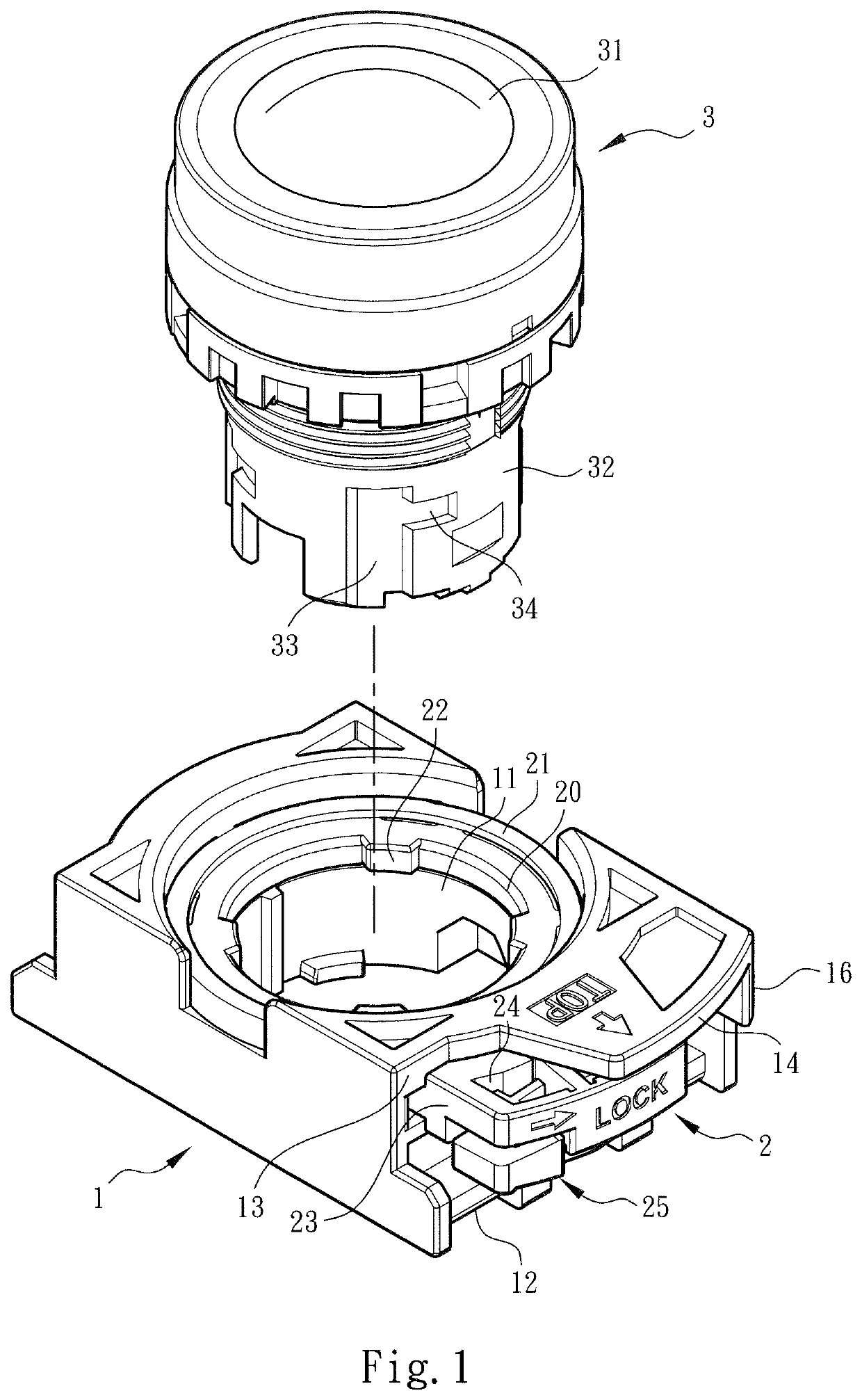
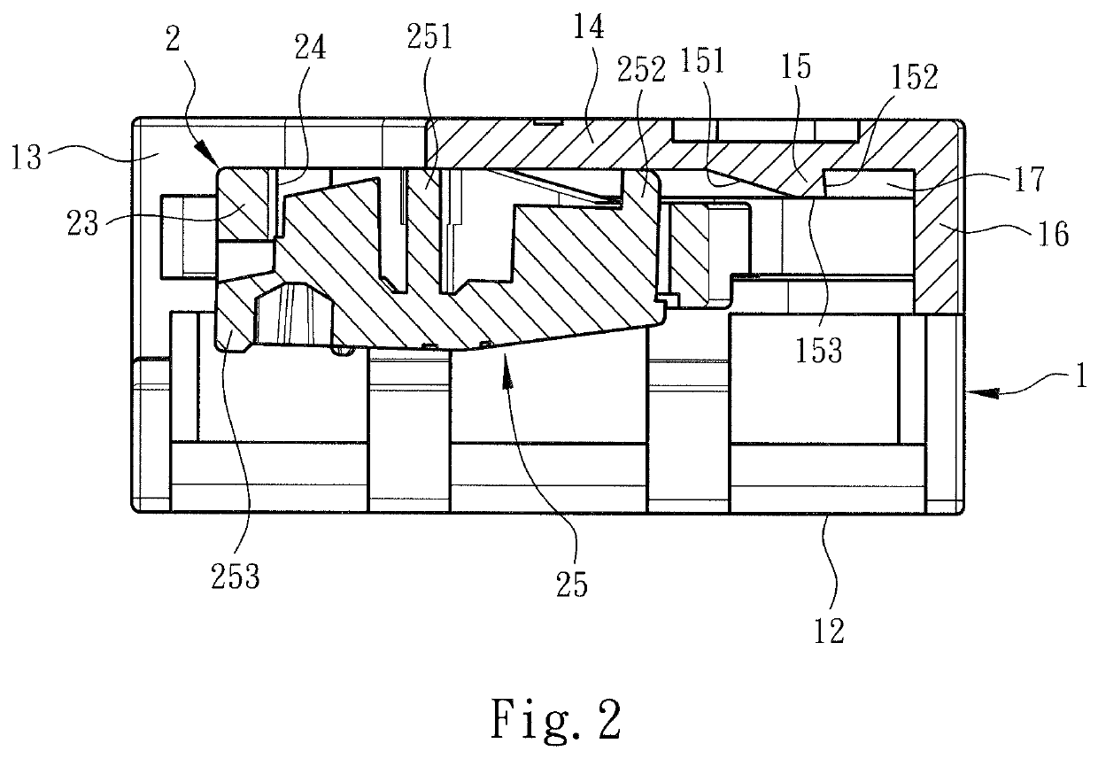
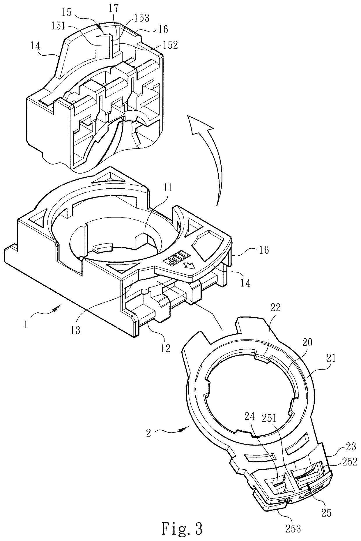
[0026]Please refer to FIGS. 1 to 3. The locking structure of switch device of the present invention includes a connection seat 1 and a shift body 2 assembled with the connection seat 1. The connection seat 1 is formed with a main body assembling hole 11. The shift body 2 is formed with a perforation 20 in communication with and in alignment with the main body assembling hole 11. The main body assembling hole 11 and the perforation 20 serve to together receive an operation section main body 3 to assemble the main body 3 with the connection seat 1. An operation section 31 is received and disposed in the main body 3 for an operator to press or rotate so as to control the switch device into a closed-circuit state or an open-circuit state. The main body 3 has a shaft section 32 and a channel 33 formed on the shaft section 32. One side of the channel 33 communicates with an end channel 34. A latch section 12 is disposed on the bottom section of the connection seat 1 for latching with mult...


PUM


Abstract

A locking structure of switch device includes a connection seat formed with a main body assembling hole. An arm protrudes from the connection seat. A restriction section is formed on the arm. A shift body is assembled on the connection seat and movable between a first position and a second position. The shift body has a shift section aligned with the arm in the second position. A lever member is disposed on the shift section. Two ends of the lever member are respectively formed with a ridge section and a push / press section. When the shift body moves from the first position to the second position, the ridge section passes over the restriction section into a locked state. When pressing the push / press section, the ridge section is driven by way of leverage to backward pass over the restriction section into an unlocked state.

Description

BACKGROUND OF THE INVENTION1. Field of the Invention[0001]The present invention relates generally to a locking structure of switch device, and more particularly to a locking structure of switch device for installing / uninstalling the operation section main body and the wire connection module. The locking structure of the switch device can be operated with less strength. In addition, the entire structure of the locking structure of the switch device can be completely enclosed.2. Description of the Related Art[0002]A conventional switch device or switch indication device is applied to an electrical, electronic and automatic control system for an operator to operate the machine or power on / off the system.[0003]For example, a conventional switch device discloses a part installation structure, in which a support body is connected with a pushbutton (an operation section) and a switch (a wire connection module). The support body is formed with a perforation for receiving the pushbutton. A r...

Claims


Application Information

Patent Timeline
Patent Type & Authority Patents(United States)
IPC IPC(8): H01H9/08H01H13/04H01H19/04H01H9/28H01H1/52
CPCH01H9/285H01H13/04H01H1/52H01H19/04H01H9/08H01H3/02H01H9/02H01H9/20
Inventor WU, CHIH-YUANHSU, WEN-BING
Owner SWITCHLAB
Features
  • R&D
  • Intellectual Property
  • Life Sciences
  • Materials
  • Tech Scout
  • Unparalleled Data Quality
  • Higher Quality Content
  • 60% Fewer Hallucinations
Learn More