Supercharge Your Innovation With Domain-Expert AI Agents!

Battery pack including spacer

a battery pack and spacer technology, applied in the direction of secondary cell servicing/maintenance, cell component details, cell components, etc., can solve the problems of insufficient prevention of battery module movement, battery pack malfunction, and battery module movement, so as to reduce the motion of the upper end parts

Active Publication Date: 2020-04-21
LG ENERGY SOLUTION LTD
View PDF51 Cites 2 Cited by
  • Summary
  • Abstract
  • Description
  • Claims
  • Application Information

AI Technical Summary

Benefits of technology

The spacer effectively stabilizes battery modules during external impacts and vibrations, while preventing condensed water from entering the pack, thereby enhancing the reliability and durability of the battery pack.

Problems solved by technology

In this structure, the battery modules may move due to vibration caused in a driving condition of a device in which the battery pack is mounted.
In the above structure, however, it is not possible to sufficiently prevent motion of the battery modules in a lateral direction thereof when vibration is generated from the battery pack in a lateral direction thereof.
In addition, since an empty space is provided between the pack housing and the battery modules, condensed water generated on the inner surface of the pack housing due to a temperature difference between the inside and the outside of the battery pack may fall to the upper ends of the battery modules with the result that the battery pack may malfunction.

Method used


Image

  • Battery pack including spacer
  • Battery pack including spacer
  • Battery pack including spacer

Examples


Embodiment Construction

[0044]Now, exemplary embodiments of the present invention will be described in detail with reference to the accompanying drawings. It should be noted, however, that the scope of the present invention is not limited by the illustrated embodiments.

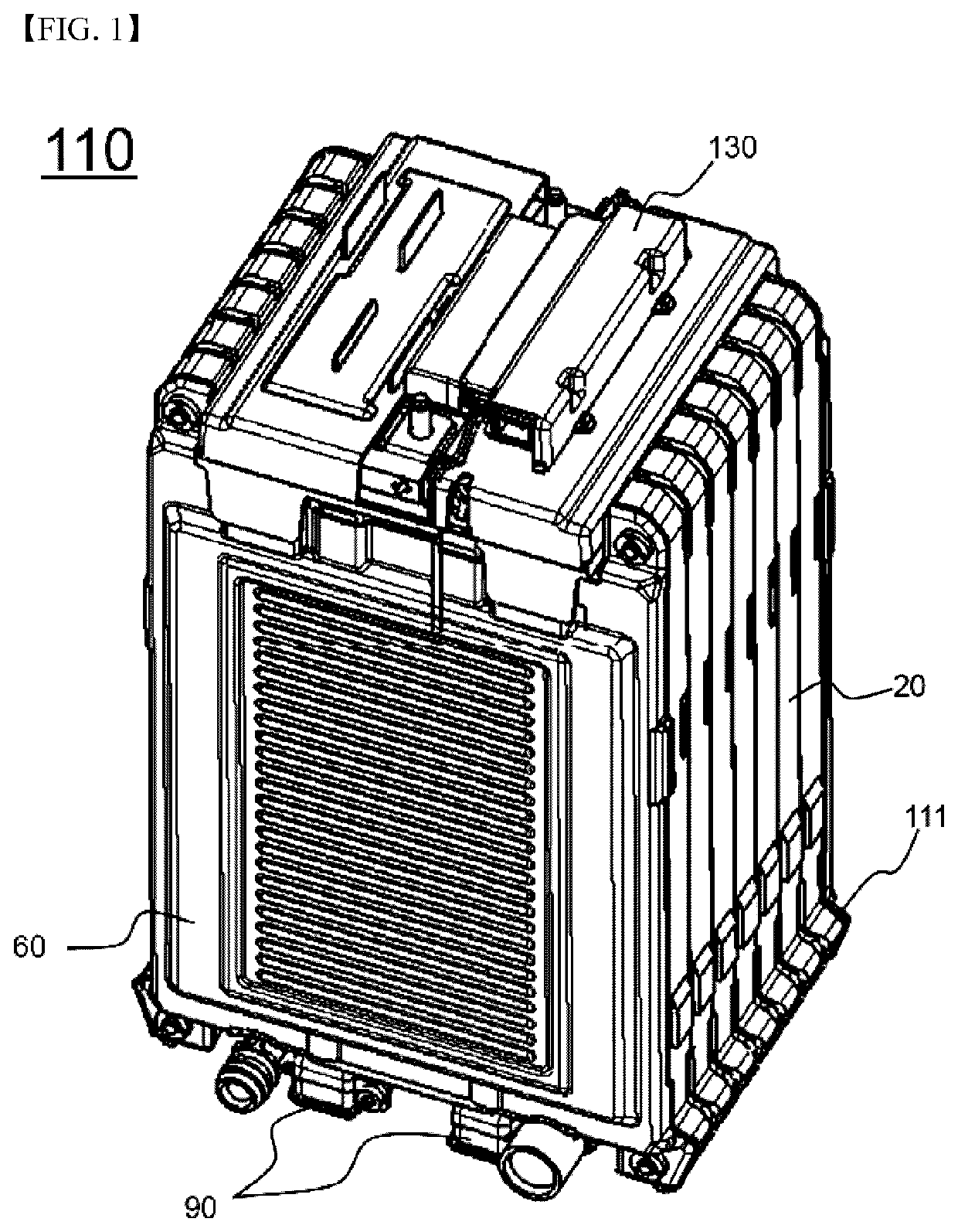
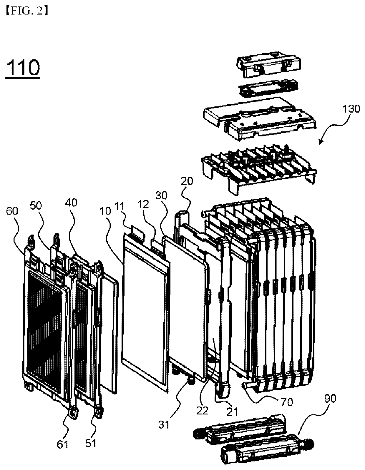
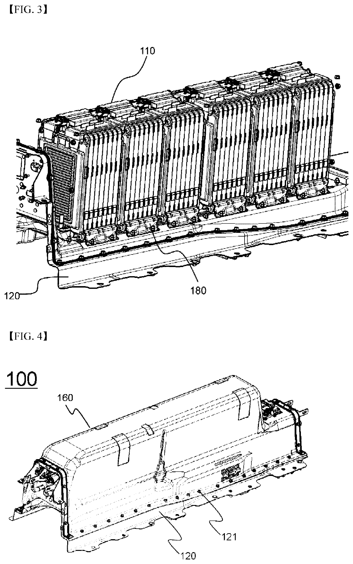
[0045]FIG. 1 is a perspective view showing a battery module according to an embodiment of the present invention, FIG. 2 is an exploded view of the battery module of FIG. 1, and FIG. 3 is a perspective view showing a battery module and a hold down bracket according to an embodiment of the present invention;

[0046]Referring to FIG. 1 and FIG. 2, a battery module (110) includes a battery cell 10, a cartridge 20, a cooling member 30, a buffer member 40, an insulation member 50, an end plate 60, a bus bar assembly 80, and a cooling manifold 90.

[0047]The battery cell 10 is configured to have a structure in which an electrode assembly is mounted in a battery case made of a laminate sheet including a metal layer and a resin layer and an outer edge of...


PUM

PropertyMeasurementUnit
voltageaaaaaaaaaa
shapeaaaaaaaaaa
heightaaaaaaaaaa

Abstract

Disclosed herein is a battery pack configured to have a structure in which two or more battery modules, each of which includes a plurality of battery cells or unit modules which can be charged and discharged, are arranged such that the battery modules are mounted in a space defined between a pack housing and a base plate, the battery pack including the base plate on which the arranged battery modules are loaded, a sensing assembly mounted at upper ends of the battery modules for detecting voltage of the battery modules, a pair of tension bars mounted at the upper ends of the battery modules in a direction in which the battery modules are arranged for supporting the battery modules, a battery management system (BMS) mounted at an outside of an outermost one of the battery modules in a state in which the BMS is adjacent to the outermost one of the battery modules, the pack housing for surrounding the battery modules and the BMS, a lower end of the pack housing being coupled to the base plate, and a spacer disposed in a space defined between an inner surface of the pack housing and outer surfaces of the battery modules for restraining motion of upper end parts of the battery modules.

Description

TECHNICAL FIELD[0001]The present invention relates to a battery pack including a spacer.BACKGROUND ART[0002]In recent years, a secondary battery, which can be charged and discharged, has been widely used as an energy source for wireless mobile devices. In addition, the secondary battery has attracted considerable attention as a power source for electric vehicles (EV) and hybrid electric vehicles (HEV), which have been developed to solve problems, such as air pollution, caused by existing gasoline and diesel vehicles using fossil fuels.[0003]Small-sized mobile devices use one or several battery cells for each device. On the other hand, middle or large-sized devices, such as vehicles, use a middle or large-sized battery pack having a plurality of battery cells electrically connected to one another because high output and large capacity are necessary for the middle or large-sized devices. In order to provide output and capacity required by a predetermined apparatus or device, a plurali...

Claims


Application Information

Patent Timeline
Patent Type & Authority Patents(United States)
IPC IPC(8): H01M2/10H01M10/48H01M10/42H01M2/02H01M50/10H01M50/105H01M50/211H01M50/262H01M50/291H01M50/293H01M50/569
CPCH01M2/1094H01M2/1022H01M10/4257H01M2/1077H01M2/1072H01M10/482H01M2/0287H01M2/0207Y02E60/10H01M50/10H01M50/124H01M50/24H01M50/293H01M50/105H01M50/291H01M50/569H01M50/262H01M50/211
Inventor LEE, YOONHEEKIM, TAE HYUCKROH, TAE HWANLEE, JIN KYUJUNG, JUNHEE
Owner LG ENERGY SOLUTION LTD
Features
  • R&D
  • Intellectual Property
  • Life Sciences
  • Materials
  • Tech Scout
  • Unparalleled Data Quality
  • Higher Quality Content
  • 60% Fewer Hallucinations
Learn More