Thermal block for heating liquids

a technology of heating liquid and heating liquid, which is applied in the direction of fluid heaters, lighting and heating apparatus, beverage vessels, etc., can solve the problems of inability to meet the needs of users, etc., and achieve the effect of stable operating temperature and short heating tim

Active Publication Date: 2020-05-05
I R C A S P A IND RESISTENZE CORAZZATE E AFFINI
View PDF27 Cites 0 Cited by
  • Summary
  • Abstract
  • Description
  • Claims
  • Application Information

AI Technical Summary

Benefits of technology

[0006]It is an object of the present invention to provide a thermal block capable of ensuring a stable operating temperature with short heating time, in all cases compatible with the specific market demands.
[0007]It is a further object of the invention to provide a thermal block in which there is an appropriate remixing of the liquid to be heated, so as to increase the heating of the liquid.
[0012]The thermal block of the present invention allows the heat exchange surface to be increased per length unit, thus improving the heat exchange between the massive block and the liquid. In particular, a turbulence is generated in the flow of liquid to be heated by virtue of the inner surface irregularities of the at least one corrugated segment, which are in contact with the liquid thus causing a remixing thereof and an improved heating. Advantageously, there is provided the possibility of varying the length of the at least one corrugated segment with respect to the total length of the tube for the passage of water, which allows to vary the thermal power exchanged as a function of the specific intended application. When several corrugated segments are provided, the exchanged thermal power can be appropriately modulated as a function of the specific application by appropriately varying the number of smooth segments and corrugated segments of the tube. Moreover, the dissipated thermal power can be increased in some zones and decreased in others in a selective manner by appropriately varying the mutual position of the corrugated segments and of the smooth segments. When over the length of the tube one or more corrugated segments are alternated with one or more smooth segments, the highest heat exchange will occur at the corrugated segment(s). However, the turbulence generated in the liquid by the corrugation can have remixing effects even in the smooth segments. Advantageously, the high heat exchange areas can be selected by varying the number of corrugated segments. The corrugated segments have inner transversal irregularities with respect to the longitudinal axis of the tube, and thus to the flowing direction of the liquid, and preferably the inner irregularities are orthogonal to the longitudinal axis of the tube. Furthermore, the irregularities can be made over the whole perimeter of a section, for example a section orthogonal to the longitudinal axis of the tube or over a part of such a perimeter. For example, if the tube has a circular orthogonal section, each irregularity can be substantially circle-shaped or substantially shaped as a circumferential arc.
[0014]Advantageously, the tube can be deformed to obtain the corrugation before it is incorporated in the massive block since the tube is a distinct element, immersed in the massive block. Thereby, the tube may be deformed in a simple, rapid manner, e.g. by applying a pressure on the outer wall thereof via appropriate means. Thereby, the inner irregularities can be further made so as to have complex geometric shapes, e.g. helixes, spirals or other. The number of corrugated segments, the shape of the irregularities and the shape of the tube can thus be easily varied as needed. Moreover, a tube folded on itself can be used so that the path of the tube is developed on two or more superimposed planes. For example, a tube shaped as a meander serpentine folded on itself at approximately half its length can be used or a tube folded on itself so as to have one portion with one or more superimposed windings, being either circular or elliptical, and in which the inlet and the outlet of the tube lay on different planes, preferably parallel to one another, can be used. The tube preferably comprises at least two curved segments.
[0015]A further advantage is in that the massive block and the tube can be made of different materials. For example, the massive block can be made of aluminum, which has excellent heat conductivity and the tube may be made of stainless steel, because it has good wear resistance, in particular corrosion resistance, and is suitable for contact with food grade liquids.
[0018]Other advantages can be obtained by means of a thermal block made in accordance with the dependent claims. In particular, the possibility of using a corrugated lining sheath for the resistive element allows to improve the heat exchange between the latter and the massive block.

Problems solved by technology

In order to satisfy such specifications, it would be necessary to maintain the heating member at a predetermined temperature; however this would imply an energy consumption which is considered unacceptable.
However, there are a plurality of drawbacks even when a thermal block is used, including operating temperature instability and excessive heating time, e.g. longer than two minutes in the case of a coffee maker.

Method used


Image

  • Thermal block for heating liquids
  • Thermal block for heating liquids
  • Thermal block for heating liquids

Examples


Embodiment Construction

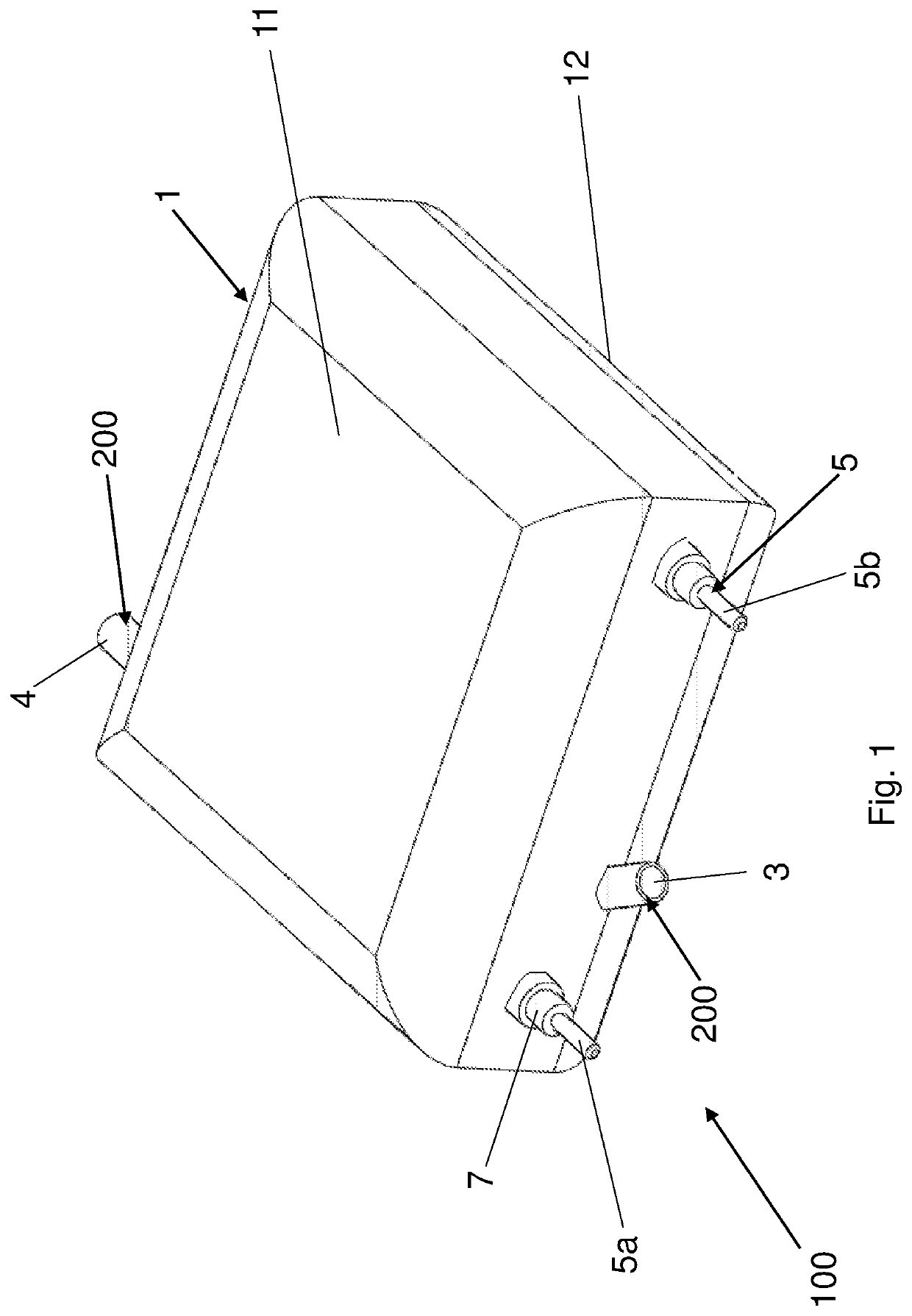
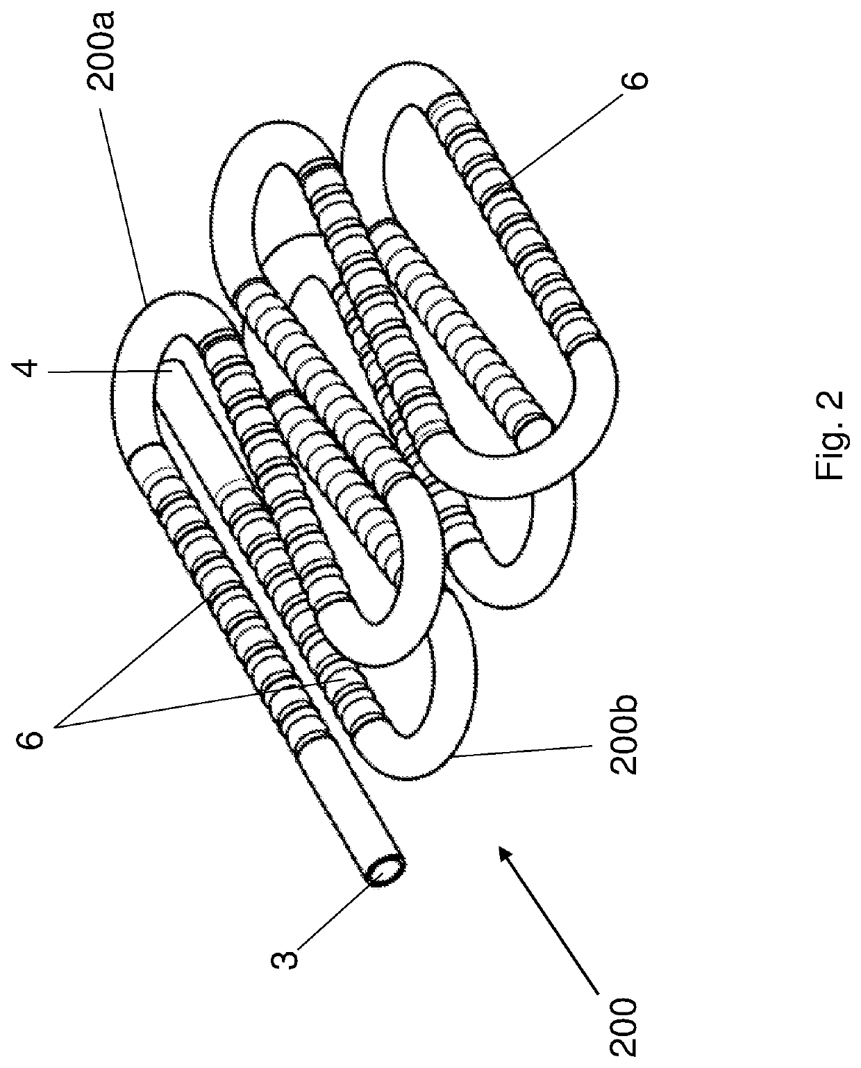
[0039]With reference to figures from 1 to 3, according to a first embodiment, a thermal block for heating a liquid, in particular water, in a home appliance is indicated as a whole by reference numeral 100.

[0040]The thermal block is generally shaped as a parallelepiped. The thermal block 100 comprises a tube 200 for the passage of water to be heated. Tube 200 is provided with an inlet 3 for the water at low temperature to be heated and an outlet 4 for the heated water. Being crossed by water for human consumption, the tube 200 is made of stainless steel. The thermal block 100 comprises a massive block 1 co-molded outside tube 200, so that the inlet 3 and the outlet 4 of tube 200 are outside the massive block 1. The massive block 1 consists of a mass of material capable of ensuring high thermal capacity, so as to accumulate the thermal energy which must be transmitted to the water, and with high thermal conductivity so as to transfer the thermal energy accumulated in the massive bloc...


PUM


Abstract

A thermal block (100) for heating a liquid, comprises: —a tube (200) for the passage of liquid, provided with an inlet (3) and an outlet (4) and with at least one segment (200) with corrugated walls (6), —a massive block (1) co-molded outside said pipe (200) so that the inlet (3) and the outlet (4) are outside the massive block (1), —one resistive element (5) for heating the massive block (1).

Description

CROSS REFERENCE TO RELATED APPLICATIONS[0001]This application is a national phase of PCT application No. PCT / IB2014 / 066314, filed Nov. 25, 2014, which claims priority to IT patent application No. PD2013A000321, filed Nov. 26, 2013, all of which are incorporated herein by reference thereto.FIELD OF THE INVENTION[0002]The present invention relates to a thermal block for heating liquids.BACKGROUND ART[0003]In many home appliance applications, in particular in small-sized appliances, for example, but not exclusively, espresso coffee makers, it is essential for a given amount of water to be available at an optimal temperature and for the water temperature to remain constant when dispensing the finished product, e.g. coffee.[0004]Furthermore, given the home and thus occasional use, the water must be heated rapidly in order to reduce the times required for dispensing the finished product and the interval of time between two subsequent dispensing operations. In order to satisfy such specifi...

Claims


Application Information

Patent Timeline
Patent Type & Authority Patents(United States)
IPC IPC(8): A47J31/54F24H1/10
CPCA47J31/542
Inventor WEDAM, STEFANOZOPPAS, FEDERICO
Owner I R C A S P A IND RESISTENZE CORAZZATE E AFFINI
Why Eureka
Try Eureka