Weighing machine for products in a packaging assembly

a technology of weighing machine and packaging assembly, which is applied in the field of weighing machines, can solve the problems of damage to fragile contents and vertical drop of fragile contents, and achieve the effect of reducing impact damage and reducing impact fall damag

Active Publication Date: 2020-05-05
BELAIR LUC
View PDF32 Cites 0 Cited by
  • Summary
  • Abstract
  • Description
  • Claims
  • Application Information

AI Technical Summary

Benefits of technology

[0006]In one embodiment, each of the plurality of feeding hoppers further comprise a first gate member, a second gate member, and a gate opening mechanism. In one embodiment, the gate opening mechanism includes an M-shaped articulated hinge member connected to the first and second gate members such that when the first gate member opens it simultaneously opens the second gate member. In another embodiment, the gate opening mechanism is a pneumatic system. In one embodiment, the products are configured to stay on the cantilevered flap during operation until a predetermined weight is reached which exceeds the effective weight of the counterweight member. In yet another embodiment, the cantilevered flap flips down and presses against the first gate member waiting the activation of the gate opening mechanism which opens the first and second gate members allowing the products to pass through the first and second gate members. In one embodiment, the plurality of weighing hoppers include a bottom surface positioned close to a top portion of the pair of alternating horizontal sliding conveyors defining a fall height, such that when the products fall from the plurality of weighing hoppers to one of the pair of alternating horizontal sliding conveyors the damage is limited.
[0008]In one embodiment, the plurality of feeding hoppers are positioned below the plurality of vibrating trays, the plurality of weighing hoppers are positioned below the plurality of feeding hoppers, the plurality of chutes are positioned below the plurality of weighing hoppers, and the pair of alternating horizontal sliding conveyors are positioned below the plurality of chutes. In another embodiment, the pair of alternating horizontal sliding conveyors and the pair of transport conveyors are comprised of a rubberized material reducing impact fall damage to the products.
[0009]In another aspect of the invention, a weighing machine for products in a packaging assembly is provided, comprising a base; a centralized cone supported in a frame; a vibrating convex disc; a plurality of vibrating trays, a plurality of feeding hoppers, a plurality of weighing hoppers, and a plurality of chutes arranged in a circular pattern; each of the plurality of feeding hoppers comprising a cantilevered flap configured to rotate around a horizontal pivot axis, a counterweight member extending opposite the cantilevered flap, the counterweight member including a plate member configured to slide along at least one groove in relation to the horizontal pivot axis to adjust an effective weight of the counterweight member, wherein the products are configured to stay on the cantilevered flap during operation until a predetermined weight is reached which exceeds the effective weight of the counterweight member a pair of alternating horizontal sliding conveyors; and a pair of transport conveyors positioned under the pair of alternating horizontal sliding conveyors, wherein each of the pair of alternating horizontal sliding conveyors are configured to alternate positions such that only one of the pair of transport conveyors is exposed underneath the pair of alternating horizontal sliding conveyors, wherein the pair of alternating horizontal sliding conveyors and the pair of transport conveyors are comprised of a rubberized material reducing impact fall damage to the products.

Problems solved by technology

The major problem appears to be in the vertical drop that the fragile contents are subject to as they go through the machine.
If the vertical drop is too high, the fragile contents are damaged when it hits a surface lying below.

Method used


Image

  • Weighing machine for products in a packaging assembly
  • Weighing machine for products in a packaging assembly
  • Weighing machine for products in a packaging assembly

Examples


Embodiment Construction

[0016]The following description is provided to enable any person skilled in the art to make and use the invention and sets forth the best modes contemplated by the inventor of carrying out their invention. Various modifications, however, will remain readily apparent to those skilled in the art, since the general principles of the present invention have been defined herein to specifically provide an improved weighing machine for products in a packaging assembly with an improved handling of fragile contents.

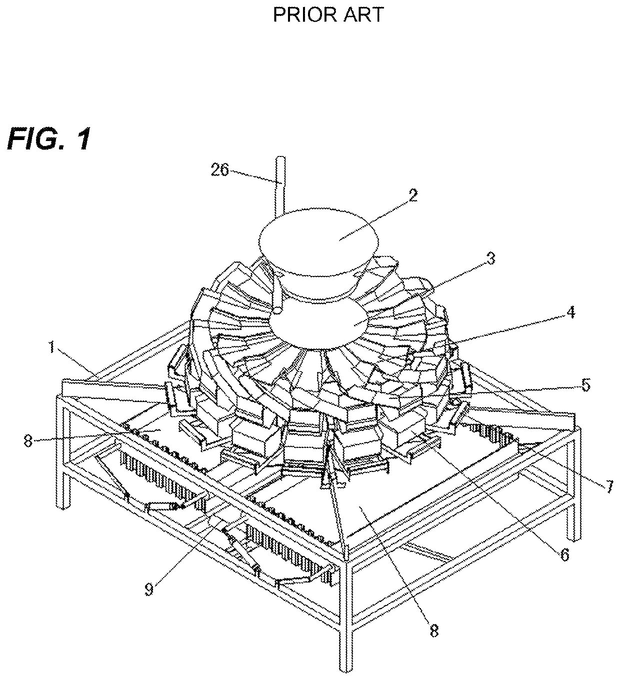
[0017]FIG. 1 is a perspective view of a weighing machine of the prior art. The weighing machine comprises a center fixed cone 2 fixed on an upper end of a frame through a supporting rod 26. A central vibrating cone 3 is arranged on a lower side of the center fixed cone. Linear vibrating trays 4 are evenly disposed under the central vibrating cone 3 on one end and at the top of sliding feeding chutes 5 at their opposite ends. The bottom of the sliding feeding chutes consists in an a...


PUM


Abstract

A weighing machine for products in a packaging assembly comprising a vibrating convex disc; a plurality of vibrating trays, a plurality of feeding hoppers, a plurality of weighing hoppers, and a plurality of chutes arranged in a circular pattern; each of the plurality of feeding hoppers comprising a cantilevered flap configured to rotate around a horizontal pivot axis, a counterweight member extending opposite the cantilevered flap, the counterweight member including a plate member configured to slide along at least one groove in relation to the horizontal pivot axis to adjust an effective weight of the counterweight member; a pair of alternating horizontal sliding conveyors; and a pair of transport conveyors positioned under the pair of alternating horizontal sliding conveyors.

Description

CROSS-REFERENCE TO RELATED APPLICATIONS[0001]N / ABACKGROUND OF THE INVENTION1. Field of the Invention[0002]The present invention generally relates to weighing machines, but more particularly to an improved weighing machine for products in a packaging assembly.2. Description of Related Art[0003]One application of a weighing machine is in the packaging industry to ensure that each package in an assembly line has the same desired weight. Since the speed and handling treatment of products are important in an assembly line, many improvements have been made to the process. Applicant has patented such a machine which is described in Chinese patent 201610860931.8, the disclosure of which is incorporated herein by reference.[0004]Although applicant's machine showed significant improvements over the prior art, most notably for its delicate handling of fragile content such as fruits and vegetables, there is still room for improvement. The major problem appears to be in the vertical drop that th...

Claims


Application Information

Patent Timeline
Patent Type & Authority Patents(United States)
IPC IPC(8): B65B37/18G01G19/393B65B1/34
CPCG01G19/393B65B37/18B65B1/34
Inventor BELAIR, LUC
Owner BELAIR LUC
Why Eureka
Try Eureka