Liquid crystal display device and method of producing liquid crystal display device

a liquid crystal display and liquid crystal technology, applied in the direction of optics, non-linear optics, instruments, etc., can solve the problems of difficulty in uniform application of alignment film material over the entire surface of the substrate, and uneven application of alignment film, etc., to suppress the uneven thickness of alignment film

Active Publication Date: 2020-05-05
SHARP KK
View PDF25 Cites 0 Cited by
  • Summary
  • Abstract
  • Description
  • Claims
  • Application Information

AI Technical Summary

Benefits of technology

[0007]The methods of applying the alignment film material are roughly classified into two methods. The first method is a roll coater method using a flexographic plate, and the second method is an ink jet method using a nozzle shot. Compared with the roll coater method, the ink jet method has advantages that positional accuracy with which the alignment film material is applied is high and an ink consumption amount is small, and is an application method suitable for achievement of high definition and frame narrowing. However, compared with the roll coater method, application unevenness tends to occur in the ink jet method.
[0009]In JP 2015-87652 A, the phenomenon that the alignment film material flows into the contact hole formed on the substrate is suppressed, and the overall thickness unevenness of the alignment film is improved. However, there is still room for improvement in order to improve film thickness unevenness occurring at the contact hole and around its periphery. In JP 2015-99201 A, a gentle taper is provided on one side of the contact hole so that the alignment film material easily flows into the contact hole through the gentle taper. However, as the distance from the center of the contact hole increases, the width of the gentle taper decreases, and an opening of the contact hole is narrow when the alignment film material flows into the contact hole. Thus, there is still room for improvement in order to facilitate the inflow of the alignment film material into the contact hole and suppress the thickness unevenness of the alignment film. In JP 2015-87600 A and JP 2015-114374 A, a gentle taper is provided around the entire circumference of the contact hole. Thus, in a high definition liquid crystal display device, there is a possibility that a designed contact hole cannot be formed due to interference between contact holes of adjacent pixels.
[0011]The present inventors have made various studies on a liquid crystal display device in which the size of a contact hole is kept small and thickness unevenness of an alignment film is suppressed, and a method of producing a liquid crystal display device, and have paid attention to the shape of a contact hole to be provided in an organic insulating film. The present inventors have found the following: a side wall surrounding a bottom portion of the contact hole provided in the organic insulating film has a first side wall portion, a second side wall portion, a third side wall portion and a fourth side wall portion in the given order in a circumferential direction of the contact hole; in a plan view, while the first side wall portion, the bottom portion and the third side wall portion are arranged in the given order on a first straight line, the second side wall portion, the bottom portion and the fourth side wall portion are arranged in the given order on a second straight line orthogonal to the first straight line; and an inclination of an upper portion of the second side wall portion is gentler than an inclination of an upper portion of each of the first side wall portion and the third side wall portion, whereby an alignment film material easily flows into the contact hole from the second side wall portion having a relatively gentle inclination at its upper portion, and in addition, the size of the contact hole can be further reduced as compared with a case where an inclination of the entire side wall surrounding the bottom portion of the contact hole is gentle. The present inventors have further found that the contact hole provided in the organic insulating film satisfies W2>L, wherein L is a distance from an upper end of the first side wall portion on the first straight line to an upper end of the third side wall portion, and W2 is a maximum distance between one upper end and the other upper end of the second side wall portion on a third straight line parallel to the first straight line, an opening through which the alignment film material passes when flowing into the contact hole from the second side wall portion can be increased, and the alignment film material can more easily flow into the contact hole. Thereby, the inventors have arrived at the solution to the above problem, completing the present invention.
[0027]The present invention can provide a liquid crystal display device in which the size of a contact hole is kept small and thickness unevenness of an alignment film is suppressed, and a method of producing a liquid crystal display device.

Problems solved by technology

Various members are complicatedly provided on a thin-film transistor substrate and a color filter substrate of a liquid crystal display device, and there are irregularities on the surface thereof.
Therefore, when an alignment film material is applied to the substrate in order to form an alignment film, it may be difficult to uniformly apply the alignment film material over the entire surface of the substrate.
Thus, film thickness unevenness (application unevenness) may occur in the alignment film.
In particular, the inflow of the alignment film material into a contact hole is not stabilized, and the thickness unevenness of the alignment film may be greatly affected in some cases.
However, compared with the roll coater method, application unevenness tends to occur in the ink jet method.
A difference occurs in the inflow of the alignment film material into the concave-convex shape, which causes the thickness unevenness of the alignment film.
In particular, the inflow of the alignment film material into the contact hole is not stabilized, which is a dominant factor of the film thickness unevenness.
An excessive alignment film material accumulates around the contact hole into which the alignment film material has not flowed, and the film thickness of the alignment film material becomes partially thick, as a result of which the film thickness unevenness may occur.
However, as the distance from the center of the contact hole increases, the width of the gentle taper decreases, and an opening of the contact hole is narrow when the alignment film material flows into the contact hole.
Thus, in a high definition liquid crystal display device, there is a possibility that a designed contact hole cannot be formed due to interference between contact holes of adjacent pixels.

Method used


Image

  • Liquid crystal display device and method of producing liquid crystal display device
  • Liquid crystal display device and method of producing liquid crystal display device
  • Liquid crystal display device and method of producing liquid crystal display device

Examples


embodiment 1

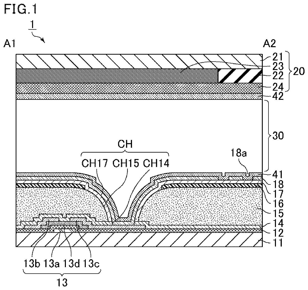
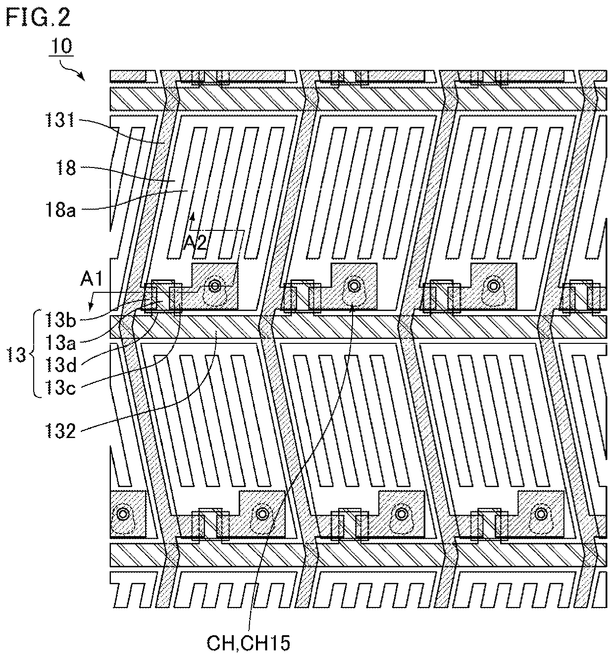
[0041]In this embodiment, an explanation will be given by taking an FFS mode liquid crystal display device as an example. FIG. 1 is a schematic cross-sectional view of the liquid crystal display device of Embodiment 1. FIG. 2 is a schematic plan view of a thin-film transistor substrate included in the liquid crystal display device of Embodiment 1. FIG. 1 is a schematic cross-sectional view taken along a line A1-A2 in FIG. 2. As shown in FIG. 1, a liquid crystal display device 1 of the present embodiment includes a thin-film transistor substrate 10, a counter substrate 20 facing the thin-film transistor substrate 10, and a liquid crystal layer 30 provided between the thin-film transistor substrate 10 and the counter substrate 20.

[0042]The thin-film transistor substrate 10 has a structure in which an insulating substrate 11, a gate insulating film 12, an inorganic insulating film 14, an organic insulating film 15, a common electrode 16, an interlayer insulating film 17, and a pixel el...

embodiment 2

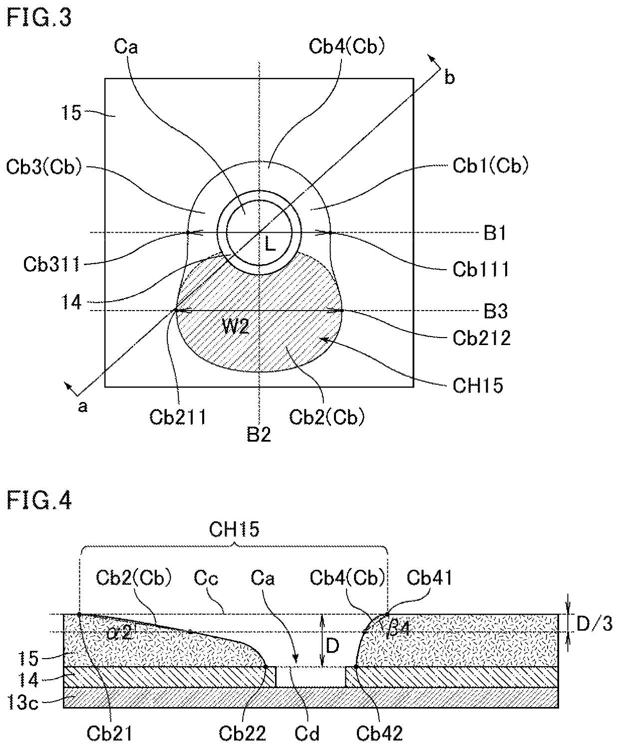
[0103]Thus, in the present embodiment, features peculiar to this embodiment will be mainly described, and description overlapping with the above embodiment will be omitted. In Embodiment 1, the inclination of the upper portion of the second side wall portion is gentler than the inclination of the upper portion of each of the first side wall portion, the third side wall portion and the fourth side wall portion. However, in the present embodiment, the inclination of the upper portion of the second side wall portion is gentler than the inclination of the upper portion of each of the first side wall portion Cb1 and the third side wall portion Cb3, and, at the same time, the inclination of the upper portion of the fourth side wall portion is gentler than the inclination of the upper portion of each of the first side wall portion Cb1 and the third side wall portion Cb3. This case will be described below.

[0104]FIG. 8 is a schematic plan view of a thin-film transistor substrate included in ...


PUM

PropertyMeasurementUnit
inclination angleaaaaaaaaaa
taper angleaaaaaaaaaa

Abstract

The liquid crystal display device according to the present invention includes: a thin-film transistor substrate, wherein the thin-film transistor substrate includes an organic insulating film disposed on a drain electrode and provided with a contact hole, the contact hole includes first, second, third, and fourth side wall portions in the given order, an inclination of an upper portion of the second side wall portion is gentler than an inclination of an upper portion of each of the first and third side wall portions, and the contact hole satisfies W2>L, wherein L is a distance from an upper end of the first side wall portion to an upper end of the third side wall portion on a first straight line, and W2 is a maximum distance between one and another upper end of the second side wall portion on a third straight line parallel to the first straight line.

Description

CROSS-REFERENCE TO RELATED APPLICATIONS[0001]The present application claims priority under 35 U.S.C. § 119 to U.S. Provisional Application No. 62 / 649,709 filed on Mar. 29, 2018, the contents of which are incorporated herein by reference in their entirety.BACKGROUND OF THE INVENTIONField of the Invention[0002]The present invention relates to a liquid crystal display device and a method of producing a liquid crystal display device. The present invention particularly relates to a liquid crystal display device having an organic insulating film provided with a contact hole, and a method of producing a liquid crystal display device.Description of Related Art[0003]The liquid crystal display device has a configuration in which a liquid crystal layer is disposed between a thin-film transistor substrate having a thin-film transistor (TFT) and a color filter substrate having a color filter. A pixel electrode is disposed on the thin-film transistor substrate, and in order to electrically connec...

Claims


Application Information

Patent Timeline
Patent Type & Authority Patents(United States)
IPC IPC(8): G02F1/1362G02F1/1337G02F1/1333G02F1/1343G02F1/1368
CPCG02F1/133711G02F1/1368G02F1/133345G02F1/136227G02F2001/133738G02F1/134363G02F1/136G02F1/1337G02F1/133707G02F1/133738
Inventor MUTO, YUTATANIIKE, KOHSHIROH
Owner SHARP KK
Why Eureka
Try Eureka