High frequency energy generator systems

a generator system and high frequency technology, applied in the field of high frequency energy generator systems, can solve problems such as more difficult to achieve, and achieve the effects of reducing the spatial requirements of the magnetrons, reducing or eliminating the need for long and/or complex waveguide structures

Active Publication Date: 2020-05-05
E2V TECH (UK) LTD
View PDF22 Cites 0 Cited by
  • Summary
  • Abstract
  • Description
  • Claims
  • Application Information

AI Technical Summary

Benefits of technology

[0007]Use of a common drive unit to supply power for a plurality of magnetrons may enable ancillary components to be combined at the common drive unit, for example, such that several magnetrons may be supplied by fewer components than would be required for separately provisioned magnetrons. Alternatively, or in addition, the same number of components may be used but more efficiently provided by being co-located at the common drive unit. Furthermore, the high frequency energy generator head including the magnetron may be more compact compared to previous configurations which deployed stand alone magnetrons each having its own power supply and other ancillary components. Thus the spatial requirements for the magnetrons may be reduced, such that, for industrial processing use, for example, it can allow greater flexibility in positioning closer to where microwaves are required, reducing or eliminating the need for long and / or complex waveguide structures. Also, the connector arrangement may be relatively flexible, for example, comprising co-axial cabling, and thus may be readily re-positioned if a head is to be moved, which can be more difficult to achieve if significant waveguide structures have to be taken into account.
[0012]In an embodiment, at least one head is positioned at a different height than another head. A system in accordance with the invention may permit the head to be more compact and lighter in weight than previous magnetron apparatus having magnetron and ancillary components combined together. Thus it provides more options for locating the heads and gives greater flexibility in designing material processing lines, for example, in which the system is deployed.
[0015]The connector arrangement comprises means to deliver power and may also include means to deliver at least one of: cooling fluid; magnetron control signalling; magnetron heater supply; safety control signalling; and electromagnet power supply. The connector arrangement may include lines for different deliverables bundled together. In another embodiment, some or all of them are combined into a single sheath, for example, providing ease of handling when deploying the system.

Problems solved by technology

Also, the connector arrangement may be relatively flexible, for example, comprising co-axial cabling, and thus may be readily re-positioned if a head is to be moved, which can be more difficult to achieve if significant waveguide structures have to be taken into account.

Method used


Image

  • High frequency energy generator systems
  • High frequency energy generator systems
  • High frequency energy generator systems

Examples


Embodiment Construction

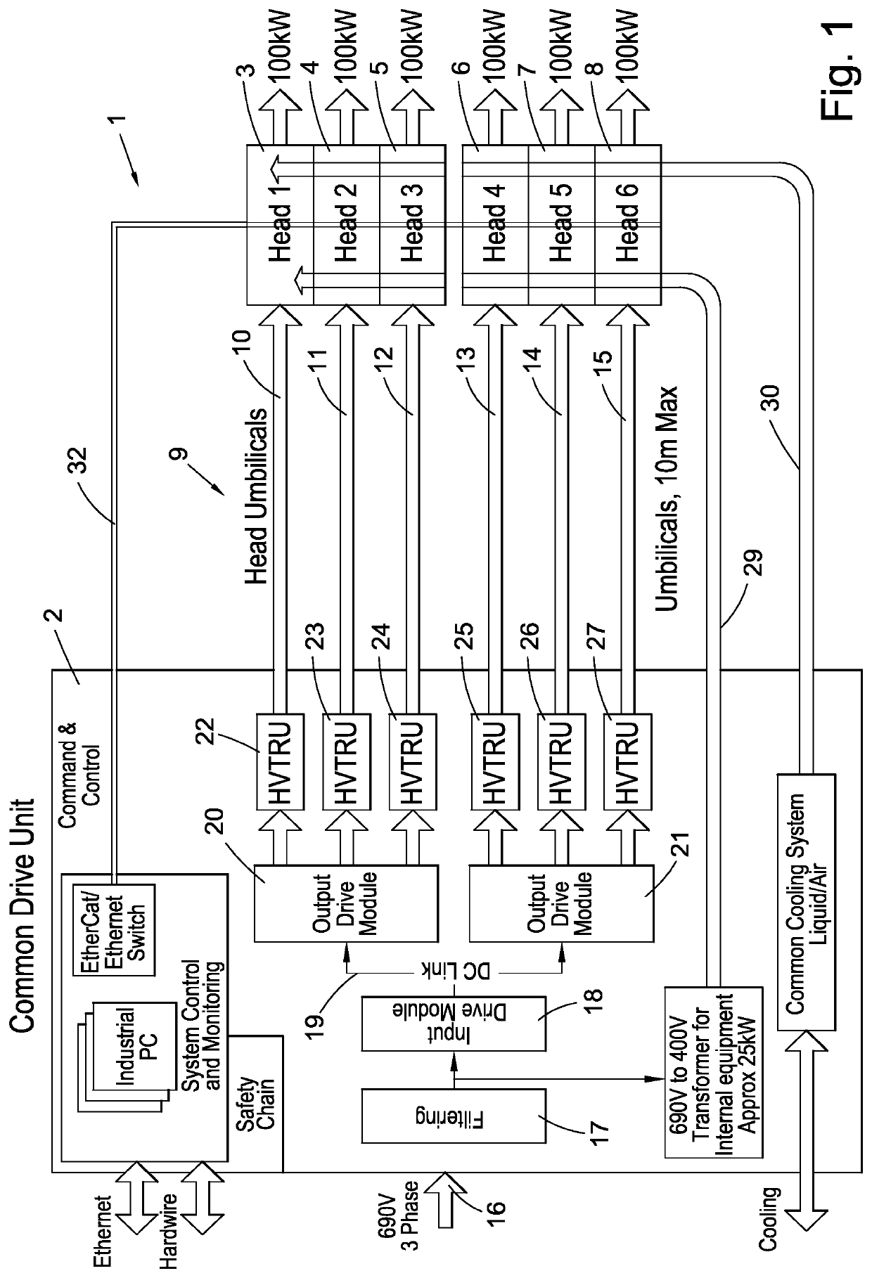
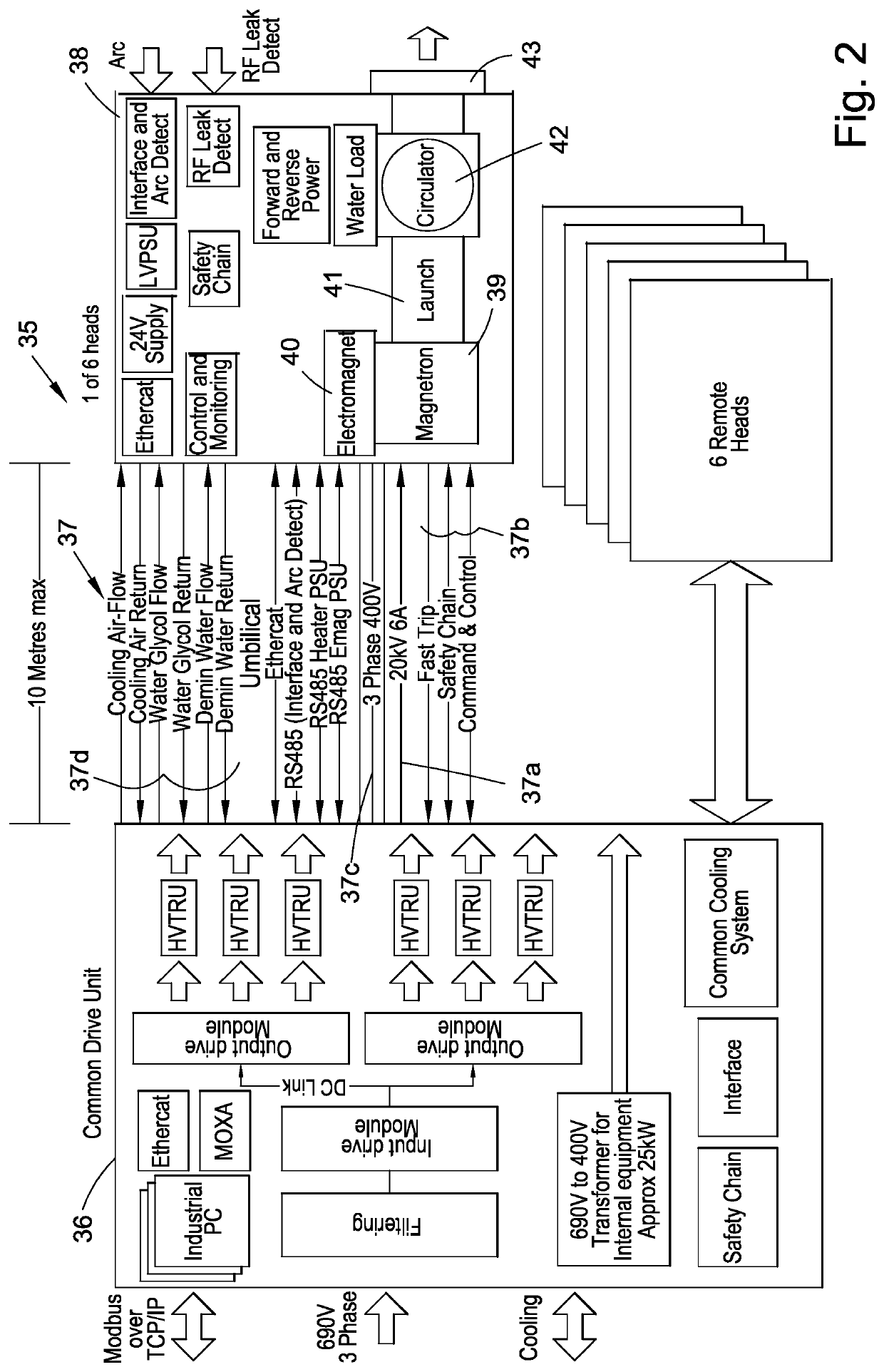
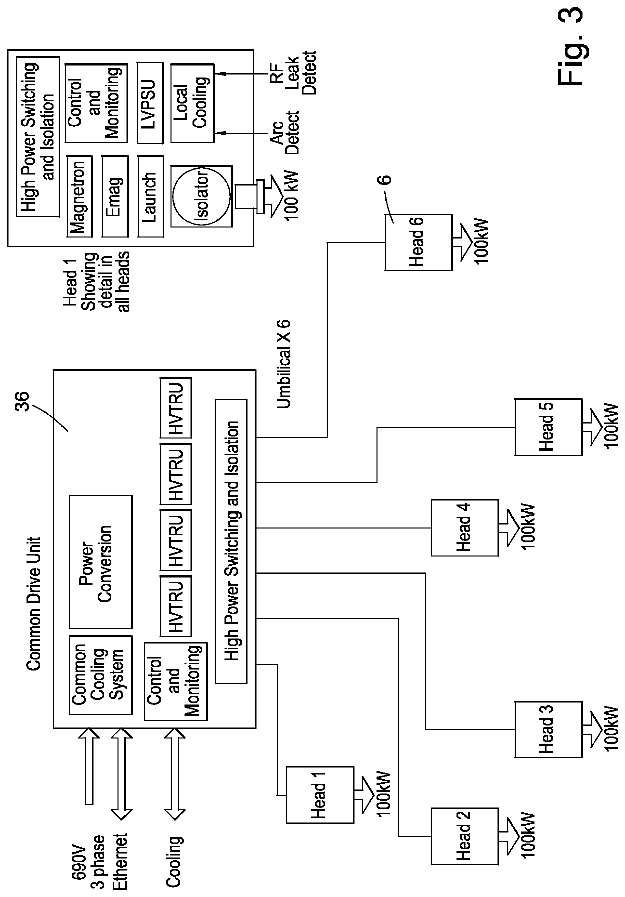
[0032]With reference to FIG. 1, a high frequency energy generator system 1 deployed for use in an industrial processing line comprises a common drive unit 2, six high frequency energy generator heads 3 to 8, each head including a respective magnetron (not shown) and a connector arrangement 9 connecting each of the heads 3 to 8 to the common drive unit 2 to supply power to the magnetrons. The connector arrangement 9 has six connectors 10 to 15, each connector being dedicated to a respective head 3 to 8.

[0033]Each head 3 to 8 is located remote from the common drive unit 2 and, in this embodiment, the connectors 10 to 15 have a maximum length of 10 m and are flexible to facilitate positioning of the heads.

[0034]A three phase electrical signal of 690V is applied to an input 16 of the common drive unit 2. The input is filtered at 17 to suppress harmonics and then applied to an input drive module 18 which has three single channels. The output of the primary drive module 18 is applied via ...


PUM

PropertyMeasurementUnit
lengthaaaaaaaaaa
voltageaaaaaaaaaa
output poweraaaaaaaaaa

Abstract

A high frequency energy generator system includes a plurality of high frequency energy generator heads. Each head includes a respective magnetron; a common drive unit for producing power for the plurality of magnetrons; and a connector arrangement connecting each of the plurality of heads to the common drive unit to supply power to the magnetrons. At least one of the heads is located remote from the common drive unit.

Description

[0001]This application is a National Stage of PCT / GB2013 / 052026, filed on Jul. 29,2013, which claims priority to GB 1213402.9, filed Jul. 27, 2012.FIELD OF THE INVENTION[0002]This invention relates to high frequency energy generator systems.BACKGROUND[0003]Microwaves may be used in industrial processing applications for heating or drying applications or to modify materials under treatment in some other way. In one application of microwave processing, for example, microwaves are used to exfoliate vermiculite by interacting with water found between layers of the material to cause expansion of the material.[0004]Magnetrons are microwave generators suitable for industrial processing purposes. In one type of processing system, a conveyor carries material along a line and several processing stages take place at different locations. Magnetrons may be set up at appropriate places in a processing line so that they are close to where the microwave processing is required. However, this may not...

Claims


Application Information

Patent Timeline
Patent Type & Authority Patents(United States)
IPC IPC(8): H05B6/66H05B6/68B29C35/08H05B6/80H05B6/78
CPCH05B6/78H05B6/664H05B6/80H05B6/66H05B2206/046H05B2206/044H05B6/642
Inventor BURLEIGH, PAUL SIMONISKANDER, STEPHEN MARK
Owner E2V TECH (UK) LTD
Why Eureka
Try Eureka