Vehicle seat member and vehicle seat

a vehicle seat and member technology, applied in the field of vehicle seat parts and vehicle seats, can solve the problems of difficult fixation of the vehicle seat on the vehicle body side, and achieve the effects of high accuracy, enhanced rigidity of the vehicle seat member, and high accuracy

Active Publication Date: 2020-05-12
SEKISUI PLASTICS CO LTD
View PDF15 Cites 3 Cited by
  • Summary
  • Abstract
  • Description
  • Claims
  • Application Information

AI Technical Summary

Benefits of technology

[0015]In an aspect of the vehicle seat member in accordance with the present invention, the foamed resin molded body is substantially rectangular in shape in plan view, and a part of the body portion of the frame member includes a portion lying along the longer-side direction of the foamed resin molded body, and further, the protrusion is formed on the portion lying along the longer-side direction of the body portion. When a foamed resin molded body is a rectangular parallelepiped, which is substantially rectangular in shape in plan view, the amount of shrinkage of the molded body is greater in the longer-side direction than in the shorter-side direction. Therefore, the operational advantage of the present invention can be achieved even more reliably in a vehicle seat with a configuration in which the aforementioned protrusion is formed on the portion of the body portion lying along the longer-side direction in which the amount of shrinkage is greater than that in the shorter-side direction.
[0016]Herein, the body portion may include only a longer-side portion, but in a more preferred aspect of the vehicle seat member in accordance with the present invention, the body portion also includes a shorter-side portion connected to the longer-side portion and lying along the shorter-side direction of the foamed resin molded body. According to such an aspect, as the body portion also includes a shorter-side portion, the longer-side portion of the body portion is restrained by the foamed resin molded body. Therefore, it is susceptible to the influence of the shrinkage along the longer-side direction of the foamed resin molded body. According to the present aspect, even in such a case, the position of the protrusion can be maintained with high accuracy since a space formed by partially punching the foamed resin is provided around a region where the protrusion is located.
[0017]According to a more preferred aspect of the vehicle seat member in accordance with the present invention in which the body portion includes a shorter-side portion, the body portion includes a pair of opposite longer-side portions and a pair of shorter-side portions connected to opposite sides of the respective longer-side portions and is formed such that the pair of longer-side portions and the pair of shorter-side portions surround an inner portion of the foamed resin molded body along an inner side of the contour of the foamed resin molded body in plan view, and at least one of the longer-side portions has the protrusion formed thereon.
[0018]According to such an aspect, as the body portion of the frame member surrounds the inner portion of the foamed resin molded body along the inner side of the contour of the foamed resin molded body, the rigidity of the vehicle seat member can be enhanced. Further, according to such an aspect, since the shorter-side portion of the body portion is also restrained by the foamed resin, the protrusion formed on the longer-side portion is also susceptible to the influence of the shrinkage of the foamed resin molded body along the shorter-side direction. However, even in such a case, since a space formed by partially punching the foamed resin is provided around a region where the protrusion is located, it follows that a gap is formed around the protrusion also in the shorter-side direction. Accordingly, the position of the protrusion in the shorter-side direction can be maintained with high accuracy.
[0019]In the vehicle seat member in accordance with the present invention, the size of the punched region can be experimentally set to an optimal value taking into consideration the shrinkage factor of the foamable resin material forming the vehicle seat member. If the region is too small, the foamable resin material may collide with the protrusion upon shrinkage of the foamable resin material, and the position of the protrusion can move due to such collision. If the punched portion is too large, the strength of the seat member becomes partially weak, and thus the seat member can become damaged. Therefore, in a preferred aspect of the vehicle seat member in accordance with the present invention, the punched region is provided in the range of 1 to 25 mm around the protrusion. With such a range, expected performance can be fully achieved when the foamed resin molded body forming the vehicle seat member is a molded body of foamable polystyrene resin, a molded body of foamable composite resin including polystyrene resin and polyolefin resin, or a molded body of foamable polyolefin resin.
[0020]A vehicle seat in accordance with the present invention includes the aforementioned vehicle seat member and an upper seat member provided above the vehicle seat member, in which the upper seat member is made of a cushion material that elastically deforms when a load is applied thereto, and the vehicle seat member is made of a foamed resin molded body with greater compressive strength than that of the upper seat member. In such an aspect, the material of the upper seat member is not limited, but is preferably soft polyurethane foam, and the foamed resin molded body forming the vehicle seat member is not limited, either, but is preferably a molded body of foamable polystyrene, a molded body of foamable composite resin including polystyrene resin and polyolefin resin, or a molded body of foamable polyolefin resin.

Problems solved by technology

In the vehicle seat with such a configuration, it is difficult to firmly fix the position of the frame member on the vehicle seat member, and thus there may be cases where a positional deviation occurs or abnormal noise occurs due to a positional deviation.
Further, due to such a positional deviation, it often becomes difficult to fix the vehicle seat on the vehicle body side.

Method used


Image

  • Vehicle seat member and vehicle seat
  • Vehicle seat member and vehicle seat
  • Vehicle seat member and vehicle seat

Examples


example 1

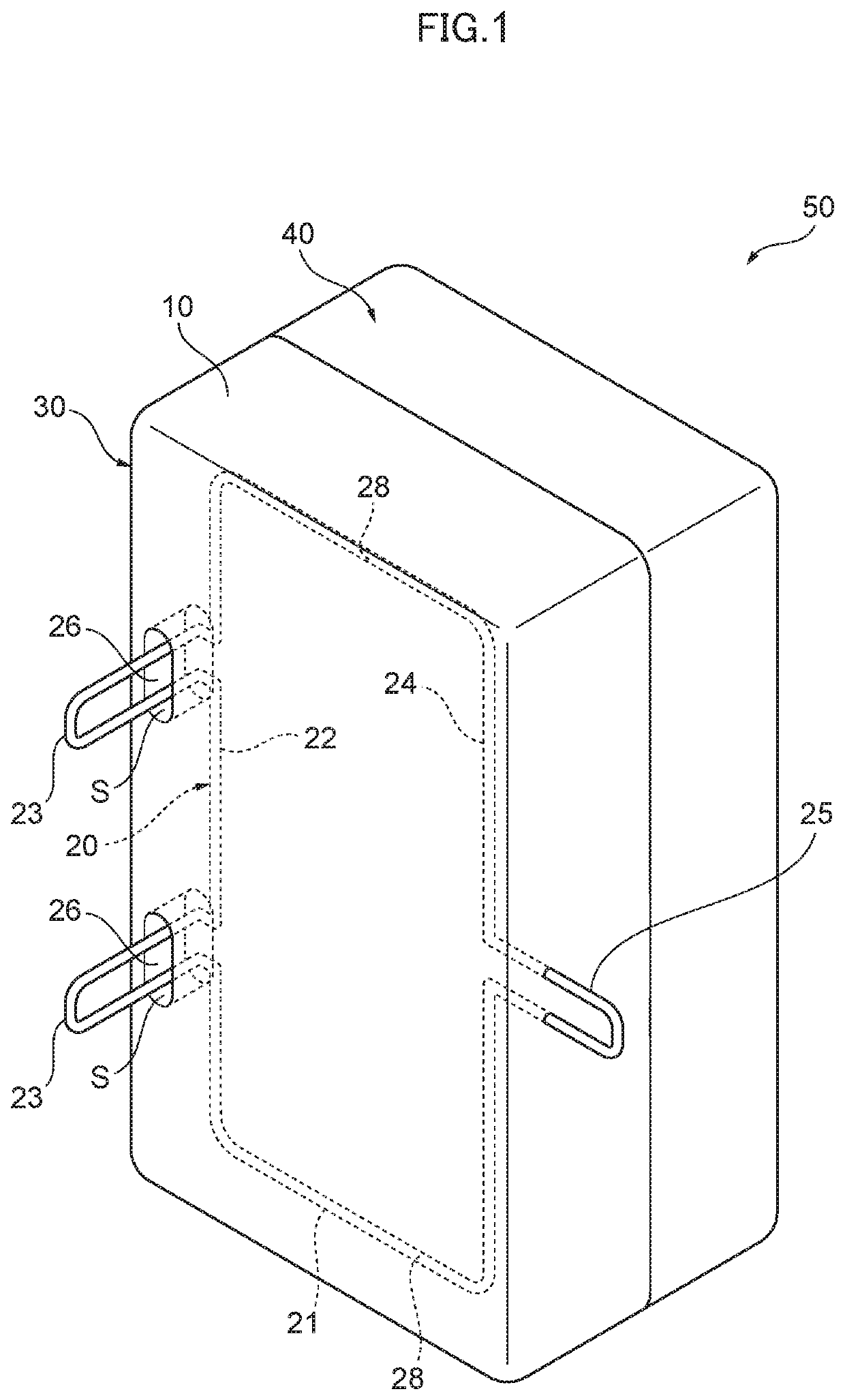
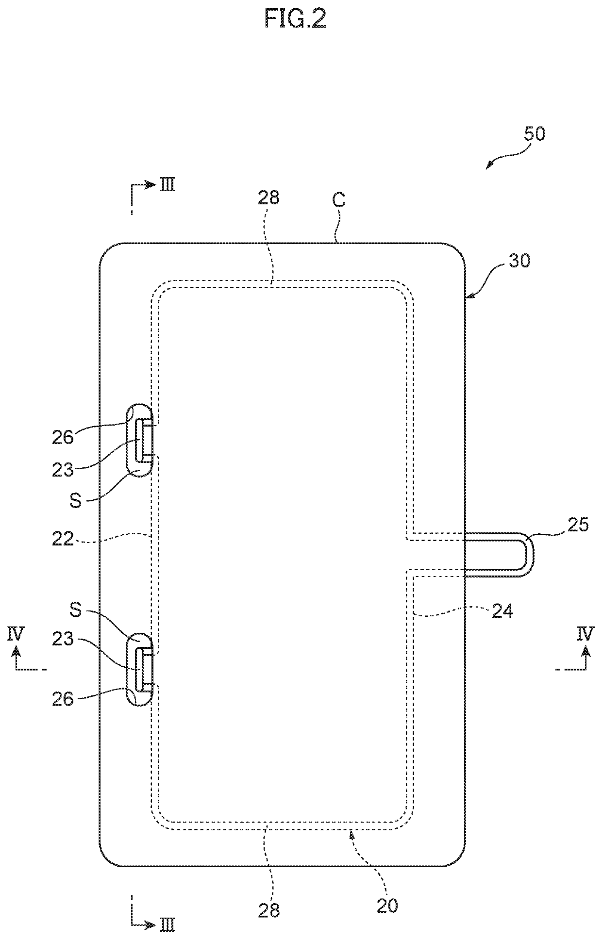
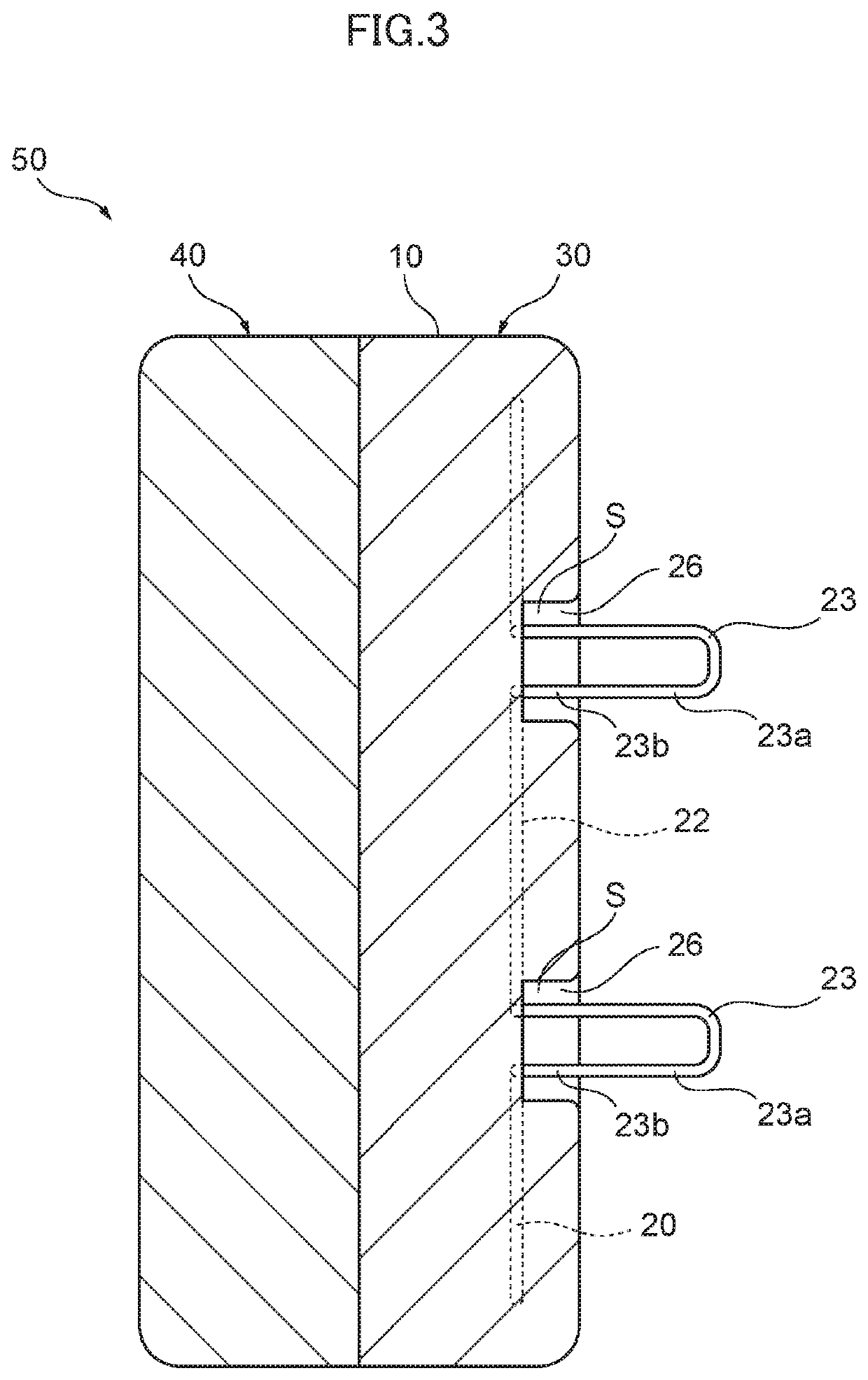
[0044]A vehicle seat member 30 with the configuration illustrated in the embodiment was produced through in-mold foam molding. The widths in the longer-side direction and the shorter-side direction of the vehicle seat member 30 were set to 1260 mm and 550 mm, respectively, and the thickness was set to 160 mm. Foamable composite resin including polystyrene resin and polyolefin resin (Piocelan (registered trademark): OP-30EU, produced by SEKISUI PLASTICS CO., Ltd.) was used as the foamable resin, and the expansion rate was set to 30 times. An iron wire (SWM-B) with a diameter of 4.5 mm was used as the frame member 20. It should be noted that the shrinkage factor of Piocelan is about 8 / 1000.

[0045]The iron wire was arranged around the entire periphery of the foamed resin molded body 10 at a position recessed inward from a peripheral side surface of the foamed resin molded body 10 by 30 mm, in almost the middle portion of the foamed resin molded body 10 forming the vehicle seat member 30...

example 2

[0048]Foamable polystyrene resin (ESLEN beads: FDK-40LV, produced by SEKISUI PLASTICS CO., Ltd.) was used as the foamable resin, and the expansion rate was set to 40 times. Then, as illustrated in the enlarged view of FIG. 5, a punched portion 26, which has a clearance of 4 mm on each side of the first protrusion 23 in the longer-side direction W of FIG. 5, and has a clearance of 2 mm on each side of the first protrusion 23 in the shorter-side direction L of FIG. 5, was formed. The other conditions were set the same as those in Example 1 to obtain a vehicle seat member 30. After the obtained molded body was demolded and 24 hours elapsed, the distance between the vertices of the two first protrusions 23, 23 was measured. Then, the distance was found to be 699.5 mm, and the amount of change in the position was found to be 0.5 mm. It should be noted that the shrinkage factor of the foamable polystyrene resin used is about 3 / 1000.

example 3

[0050]Foamable polypropylene resin was used as the foamable resin, and the expansion rate was set to 30 times. Then, as illustrated in the enlarged view of FIG. 5, a punched portion 26, which has a clearance of 18 mm on each side of the first protrusion 23 in the longer-side direction W of FIG. 5, and has a clearance of 10 mm on each side of the first protrusion 23 in the shorter-side direction L of FIG. 5, was formed. The other conditions were set the same as those in Example 1 to obtain a vehicle seat member 30. After the obtained molded body was demolded and 24 hours elapsed, the distance between the vertices of the two first protrusions 23, 23 was measured. Then, the distance was found to be 699.5 mm, and the amount of change in the position was found to be 0.5 mm. It should be noted that the shrinkage factor of the foamable polypropylene resin used is about 18 / 1000.


PUM

PropertyMeasurementUnit
diameteraaaaaaaaaa
thicknessaaaaaaaaaa
thicknessaaaaaaaaaa

Abstract

Provided are a vehicle seat member in which even when a foamed resin molded body forming the vehicle seat member shrinks after being demolded, influence of the shrinkage behavior on a frame member embedded in the foamed resin molded body can be prevented, and thus a change in the position of a protrusion, which serves as a part to be anchored to a vehicle body, of the frame member can be prevented, whereby the vehicle seat member can be attached to the vehicle body side easily and reliably, and a vehicle seat including such a vehicle seat member. A vehicle seat member includes a foamed resin molded body and a frame member integrally formed therewith, the frame member including a body portion embedded in the foamed resin molded body and protrusions each protruding from the body portion and having a tip end protruding outward from the foamed resin molded body.

Description

TECHNICAL FIELD[0001]The present invention relates to a vehicle seat member and a vehicle seat.BACKGROUND ART[0002]As a vehicle seat for automobiles and the like, a vehicle seat is known that includes at least a vehicle seat member having a foamed resin molded body and a frame member integrally molded therewith, the frame member including a body portion and a protrusion, the body portion being embedded in the foamed resin molded body, and the protrusion protruding from the body portion and having a tip end that protrudes outward from the foamed resin molded body. In addition, another vehicle seat is known that further includes an upper seat member stacked on such a vehicle seat member, the upper seat member being made of a cushion material that elastically deforms when a load is applied thereto, and the compressive strength of the vehicle seat member being greater than that of the upper seat member.[0003]Patent Literature 1 and Patent Literature 2 each describe a vehicle seat with t...

Claims


Application Information

Patent Timeline
Patent Type & Authority Patents(United States)
IPC IPC(8): B29C44/12B29C37/00B60N2/68B60N2/015B60N2/90B60N2/70B29K25/00B29L31/58
CPCB60N2/90B29C37/005B29C44/1271B29C44/1214B60N2/7017B60N2/015B29C44/1233B60N2/68B29K2025/06B29L2031/58B60N2/682
Inventor SAKAKIBARA, YUSHI
Owner SEKISUI PLASTICS CO LTD
Why Eureka
Try Eureka