Bypass turbomachine fitted with bleed system

a technology of bleed system and turbine engine, which is applied in the direction of machines/engines, mechanical equipment, liquid fuel engines, etc., can solve the problems of requiring bulky control means, heavy doors, and synchronised control, and achieve the effect of preventing load losses in this zon

Active Publication Date: 2020-05-12
SN DETUDE & DE CONSTR DE MOTEURS DAVIATION S N E C M A
View PDF17 Cites 0 Cited by
  • Summary
  • Abstract
  • Description
  • Claims
  • Application Information

AI Technical Summary

Benefits of technology

[0011]The invention thus makes it possible to resolve the prior art problem linked with the load losses of a bleed system of the “slot” type. The rings are here situated on this slot and the internal ring, that extends in the extension of the casing, makes it possible to “close off” the slot and to prevent the load losses in this zone. The internal ring thus reproduces a portion of the casing, or is fully integral with the latter, which is advantageous from an aerodynamic point of view. In addition, the actuator of the control of the external ring is situated outside the bleed air flow and the primary and secondary stream and therefore is not likely to generate load losses in these streams.

Problems solved by technology

Systems with doors are heavy and require synchronised control to operate the doors.
They therefore require means of control that can be bulky, with complex kinematics.
In addition, for systems with scooping doors, it is difficult to provide a seal.
This zone Z substantially disturbs the flow of the primary stream and causes disturbing load losses.

Method used


Image

  • Bypass turbomachine fitted with bleed system
  • Bypass turbomachine fitted with bleed system

Examples


Embodiment Construction

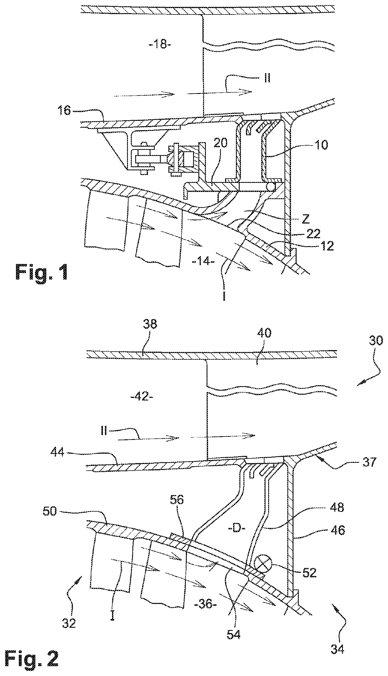
[0027]FIG. 1 has been described above and shows the prior art.

[0028]FIG. 2 is a partial schematic view as an axial cross-section of a bypass turbine engine 30. Such a turbine engine comprises in general, from the upstream to the down stream along the direction of the flow of the gases, a low pressure compressor 32, a high pressure compressor 34, a combustion chamber (not visible), a high pressure turbine (not visible) and a low pressure turbine (not visible), which define a flow duct 36 of a primary stream of gas I.

[0029]The rotor of the high pressure turbine is secured to the rotor of the high pressure compressor 34 so as to form a high pressure body, while the rotor of the low pressure turbine is secured to the rotor of the low pressure compressor 32 so as to form a low pressure body, such that each turbine drives the associated compressor in rotation about a longitudinal axis of the turbine engine under the effect of the thrust of the gases coming from the combustion chamber.

[003...


PUM


Abstract

A bypass turbine engine is described. The engine includes a system for bleeding gas from a primary stream to a secondary stream. The system may include two coaxial rings extending one around the other. A perforated internal first ring may be situated at the level of an outer casing and may extend substantially in a continuation of the outer casing. A perforated external second ring may be mounted such that it slides circumferentially on the first ring between a first position in which the perforations of the rings do not communicate with one another and a second bleed position in which the perforations of the rings communicate with one another.

Description

TECHNICAL FIELD[0001]The present invention relates to a bypass turbine engine fitted with a bleed system.STATE OF THE ART[0002]The state of the art comprises in particular documents DE-C-879 280, FR-A1-2 349 740, EP0374004, FR-A1-2 976 022, FR-A1-2 982 904, and FR-A1-3 020 400.[0003]A bypass turbine engine comprises a flow duct of a primary stream or hot stream and a flow duct of a secondary stream or cold stream. It is known to fit such a turbine engine with a bleed system or VBV system (Variable Bleed Valve) intended to regulate the flow rate of air intake into the primary duct in order, in particular, to limit the risks of pumping of the compressor of the turbine engine by making it possible for the evacuation or the bleeding of an air flow into the secondary duct. In addition, in case of accidental penetration of water into the primary duct in particular in the form of rain or hail, or of various debris, which are likely to damage the operation of the turbine engine, these syste...

Claims


Application Information

Patent Timeline
Patent Type & Authority Patents(United States)
IPC IPC(8): F01D17/10F01D17/14F02C6/08F04D27/02F04D29/54
CPCF01D17/141F01D17/105F05D2270/101F04D29/545F04D27/0215F02C6/08
Inventor LE MARECHAL, ERIC PIERRE GEORGESAGNERAY, XAVIER JEAN YVES ALAINPAPIN, THIERRY GEORGES PAULVAN GANSEN, MATHIEU DANIEL MARIEZACCARDI, CÉDRIC
Owner SN DETUDE & DE CONSTR DE MOTEURS DAVIATION S N E C M A
Why Eureka
Try Eureka