System for controlling variable-setting blades for a turbine engine

a turbine engine and variable-setting technology, which is applied in the direction of machines/engines, mechanical apparatus, liquid fuel engines, etc., can solve the problems of reducing the number of parts in the system, affecting the efficiency of the system, and causing the maximum hysteresis in all the flight envelopes, so as to achieve accurate optimal adjustment, reduce the number of parts, and minimise the effect of clearan

Active Publication Date: 2020-05-12
SN DETUDE & DE CONSTR DE MOTEURS DAVIATION S N E C M A
View PDF6 Cites 0 Cited by
  • Summary
  • Abstract
  • Description
  • Claims
  • Application Information

AI Technical Summary

Benefits of technology

[0011]The radial orientation of the linking shaft allows the bulk (and therefore the mass) of the linking means and of the control system to be limited as a whole. This particularly can allow the actuation means to approach the one or more control rings. This also allows the clearances to be minimised and the number of parts for the system to be reduced, in order to achieve more accurate optimal adjustment in order to satisfy the requirements of the laws imposed by aerodynamics.
[0012]Linking the shaft to one or more casing(s) allows the forces to be better transferred towards this one or more casing(s). Linking the radially external end of the arm to the casing allows, for example, the forces applied to the radial shaft during operation to be picked-up.

Problems solved by technology

In the prior art, the actuation means are connected to one or more control ring(s) by relatively complex and bulky linking means.
These linking means generally comprise many parts and relatively large assembly clearances, which leads to maximum hysteresis in all the flight envelopes.

Method used


Image

  • System for controlling variable-setting blades for a turbine engine
  • System for controlling variable-setting blades for a turbine engine

Examples


Embodiment Construction

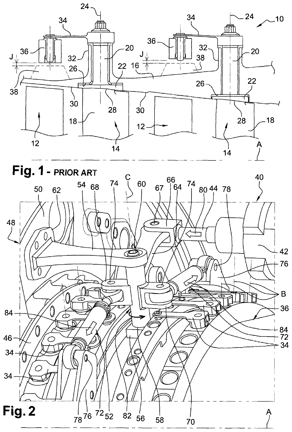
[0027]FIG. 1 schematically shows, in an axial section, part of a high-pressure compressor 10 of a turbine engine, particularly an aircraft turbine engine, with several stages, each stage comprising an annular row of movable vanes 12 supported by the rotor (not shown) of the turbine engine and an annular row of fixed vanes 14 forming rectifiers supported by a casing 16 of the stator of the turbine engine, the angular orientation of the vanes 14 being adjustable in order to optimise the gas flow in the compressor 10.

[0028]Each vane 14 comprises a blade 18 and a radially external cylindrical pivot 20 connected by a disc or “plate”22 extending perpendicular to the axis 24 of the vane in a corresponding housing 26 of the casing 16. The radially internal surface 28 of the disc is aligned with the internal wall 30 of the casing so as not to oppose the gas flow.

[0029]In the prior art, the cylindrical pivot 20 of each vane 14 extends inside a radial cylindrical chamber 32 of the casing 16 an...


PUM


Abstract

The invention relates to a system for controlling variable-setting blades (14) for a turbine engine, which includes at least one control ring (36) mounted rotatably mobile about an annular casing (16) with axis of revolution A, at least one annular row of variable-setting blades (14) extending substantially radially relative to said axis A and connected to said at least one control ring so that a rotation of the ring about the casing rotates the blades about substantially radial axes B, and means (40) for actuating said at least one ring in order to rotate same about the casing, characterised in that said actuation means are connected to said at least one ring by linking means comprising a shaft (52) extending along an axis C which is substantially radial relative to said axis A and mounted rotatably mobile about said axis C on the housing.

Description

TECHNICAL FIELD[0001]The present invention relates to a system for controlling variable pitch vanes for a turbine engine.PRIOR ART[0002]The prior art particularly comprises documents FR-B1-2885968, FR-A1-2928979, JP-U-S6119640, EP-A1-1489267, FR-A1-2983924 and EP-A2-0909880 and WO-A1-2009 / 133297.[0003]In the present application, the axis (longitudinal) of the turbine engine is defined as being the axis of rotation of the one or more rotor(s) of its engine, and in particular the rotors of its low- and high-pressure spools in the case of a twin-spool turbine engine. Terms such as internal, external, radial, axial, etc., refer to the position of a part relative to this axis.[0004]The Variable Stator Vanes (VSV) of a turbine engine are supported by an external annular casing, generally a compressor of the turbine engine. Each vane comprises a blade that is connected at its radially external end to a radial cylindrical pivot that defines the axis of rotation of the vane and is rotational...

Claims


Application Information

Patent Timeline
Patent Type & Authority Patents(United States)
IPC IPC(8): F01D17/16
CPCF01D17/162F05D2220/323F05D2260/50F04D29/563Y02T50/60
Inventor BROMANN, ALAIN MARC LUCIENBENDERRADJI, KAMELDUMAS, LILIAN YANNREICHERT, PAMELA DOMINIQUE DANIELE
Owner SN DETUDE & DE CONSTR DE MOTEURS DAVIATION S N E C M A
Why Eureka
Try Eureka