Hydraulic system

a hydraulic system and hydraulic valve technology, applied in the direction of propulsion parts, transportation and packaging, tractor vehicle steering, etc., can solve the problems of high additional weight, high level of control both for the pumps and the hydraulic valves, and the negative increase in the total weight of the combination of tractor vehicle and trailer, so as to increase the maximum pressure, reduce the weight of the hydraulic system, and be easily adaptable

Active Publication Date: 2020-05-19
SAF HOLLAND GMBH
View PDF28 Cites 1 Cited by
  • Summary
  • Abstract
  • Description
  • Claims
  • Application Information

AI Technical Summary

Benefits of technology

[0005]Preferably, the auxiliary drive and the hydraulic pump are arranged in an open hydraulic circuit. An open hydraulic circuit is characterized in that an expansion or storage tank is provided. Here, the hydraulic pump is fed from said storage tank. In order to increase the maximum pressure in the hydraulic system, the storage tank itself can be pressurized with a pressure of approximately 2 to 3 bar. The advantage of an open hydraulic circuit is that this can be easily adapted to a different or variable number of hydraulically operated systems in that the volume of hydraulic fluid in the storage tank, or the storage tank itself, is simply adapted. Furthermore, it is preferably also possible to provide a multiplicity of storage tanks both on the tractor vehicle also a multiplicity of storage tanks both on the tractor vehicle and on the trailer in order in particular to be able to expediently use the installation space in the region of the vehicle.
[0006]Preferably, during the normal operation of the utility vehicle, only one hydraulic pump on the tractor vehicle is in operation. Thus, advantageously, apart from the hydraulic pump of the hydraulic circuit on the tractor vehicle, no further hydraulic pump is provided on the tractor vehicle or on the trailer. In this way, it is possible in particular for the production price of the hydraulic system and also the weight of the hydraulic system to be significantly reduced. In other words, the hydraulic pump operates all the hydraulically operated systems provided in the hydraulic system, such as for example the auxiliary drive, a hydraulically operated tailgate, a sliding floor or the tipping function at a trailer provided for bulk materials.
[0007]It is advantageous if the first valve arrangement actuates the auxiliary drive and / or a further hydraulically operated system. Here, the first valve arrangement is preferably a valve block which controls the supply of hydraulic energy for individual hydraulically operated systems. In particular, in this case, the first valve arrangement opens up a hydraulic fluid path for a specific hydraulically operated system connected to the hydraulic system or blocks said path.
[0008]The first valve arrangement is advantageously arranged and fixed on the trailer. In this preferred case, the first valve arrangement controls the hydraulically operated systems, which are provided on the trailer. Such a hydraulically operated system is for example a tipping device for a trailer designed as a bulk materials carrier, or a hydraulically operated tailgate, or the auxiliary drive. For this preferred case, it is merely necessary for the trailer to be provided with a feed line and a discharge line for hydraulic fluid in order to be able to connect said lines to corresponding hydraulic lines of a tractor vehicle. In this way, the trailer is designed for being connected in a simple manner to the hydraulic system of a tractor vehicle and for being able to use said system for a preferred multiplicity of hydraulically operated systems on the trailer.
[0009]The hydraulic pump is advantageously driven directly or indirectly by a primary drive of the tractor vehicle. The main drive motor is particularly preferably defined as the primary drive of the tractor vehicle, which main drive motor also ensures the propulsion of the wheels of the tractor vehicle. It is preferably the case here that the hydraulic pump is mechanically connected to the motor via a gearing, wherein a coupling may be provided, in order for hydraulic pump to be put out of operation when the hydraulic system is not required. Alternatively, the hydraulic pump may also be electrically operated and connected to the alternator or the electrical power generator of the tractor vehicle. The overall efficiency of the tractor vehicle can be improved in that the hydraulic pump does not require a separate drive, such as for example an additional internal combustion engine.
[0010]Preferably, a second valve arrangement, which is designed for setting the running direction of the auxiliary drive, is provided on the trailer. While the first valve arrangement activates or deactivates the supply of hydraulic energy to the auxiliary drive, the second valve arrangement is provided in particular for setting a specific direction of movement of the auxiliary drive. Like the first valve arrangement, the second valve arrangement is preferably arranged on the trailer, and thereby in the preferably direct vicinity of the auxiliary drive, in order in particular to keep as short as possible the hydraulic lines to be routed between the auxiliary drive and the second valve arrangement. In this way, the weight of the hydraulic system can in turn be reduced. In one preferred variant, it is also possible for the first and second valve arrangements to be combined in a common valve system or valve block.

Problems solved by technology

A disadvantage in the case of such a hydraulic circuit additionally introduced on the motor vehicle is the high additional weight and a high level of outlay in terms of control both for the pumps and for the hydraulic valves.
In particular for the case of a trailer which is coupled to a tractor vehicle, wherein the tractor vehicle has a separate hydraulic system, the additional device of a further hydraulic circuit for operating an auxiliary drive brings about a particularly negative increase in the total weight of the combination of tractor vehicle and trailer.

Method used


Image

  • Hydraulic system

Examples


Embodiment Construction

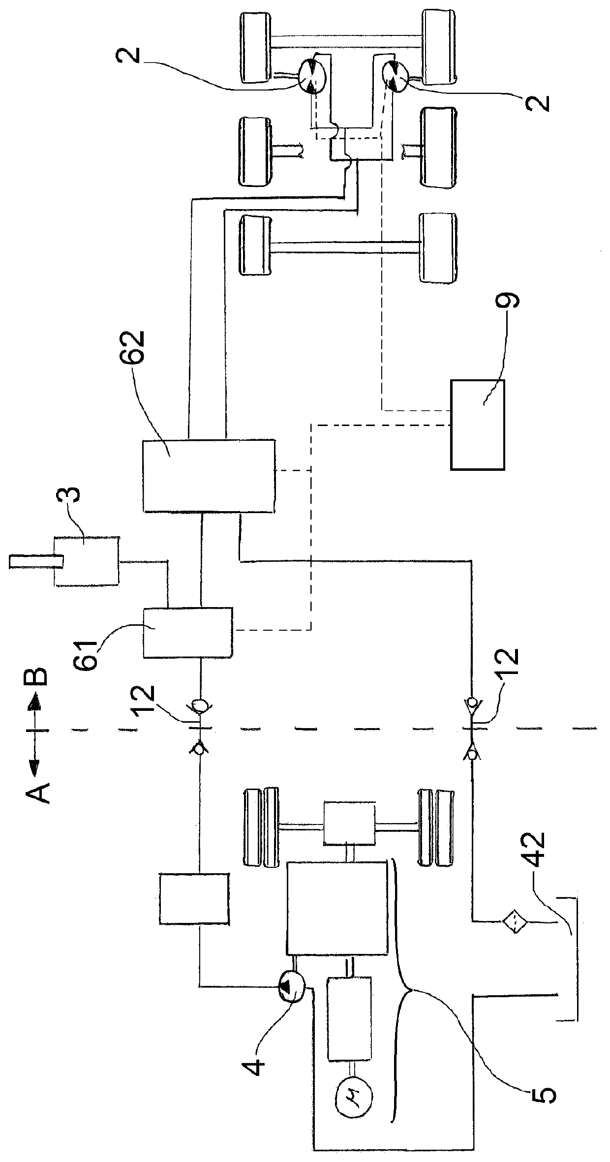
[0018]FIG. 1 schematically shows a hydraulic system which extends over the basic assemblies of tractor vehicle A and trailer B. Hydraulic couplings 12 are provided in the connection or coupling region between the tractor vehicle A and the trailer B. Said couplings are, as illustrated schematically, preferably provided with check valves, in order, in the event that the lines are separated from one another, to prevent hydraulic fluid from escaping from one of the two line parts. The hydraulic pump 4 is arranged in the region of the tractor vehicle A and, in the present preferred exemplary embodiment, is mechanically coupled to the gearing of the primary drive 5 of the tractor vehicle A. Here, the hydraulic pump 4 draws hydraulic fluid out of the storage tank 42, this likewise preferably being arranged and fixed in the region of the tractor vehicle A. By means of the storage tank 42, the hydraulic system 1 is designed as an open hydraulic circuit. Provided in the region of the trailer ...


PUM


Abstract

A hydraulic system for utility vehicles includes an auxiliary drive, a hydraulic pump and a first valve arrangement, wherein, in an operating mode, the auxiliary drive is supplied with hydraulic energy by the hydraulic pump via the first valve arrangement, wherein, in addition to the auxiliary drive, the hydraulic pump supplies at least one further hydraulically operated system with hydraulic energy, wherein the hydraulic pump is arranged on a tractor vehicle, and wherein the auxiliary drive is arranged on a trailer, which is able to be coupled to the tractor vehicle.

Description

BACKGROUND OF THE INVENTION[0001]The present invention relates to a hydraulic system for operating an auxiliary drive, and to a utility vehicle having such a hydraulic system.[0002]Hydraulically operated auxiliary drives are known per se from the prior art. Here, the formation of the auxiliary drives via completely separate hydraulic circuits, normally designed as a closed hydraulic circuit, has become established. The advantage of this actuation of the hydraulic auxiliary drive by a separate hydraulic circuit is that the auxiliary drive is able to be operated substantially independently of the hydraulic system of the motor vehicle. A disadvantage in the case of such a hydraulic circuit additionally introduced on the motor vehicle is the high additional weight and a high level of outlay in terms of control both for the pumps and for the hydraulic valves. In particular for the case of a trailer which is coupled to a tractor vehicle, wherein the tractor vehicle has a separate hydrauli...

Claims


Application Information

Patent Timeline
Patent Type & Authority Patents(United States)
IPC IPC(8): B60K7/00B62D13/00B60D1/64
CPCB60D1/64B60K7/0015B62D13/00B60K2007/0061B60Y2200/14B60Y2200/148B60Y2200/147
Inventor HÖSSLE, FLORIANCHRIST, ARMIN
Owner SAF HOLLAND GMBH
Why Eureka
Try Eureka