Attaching structure for stabilizer of utility vehicle

a technology for utility vehicles and stabilizers, which is applied in the direction of monocoque constructions, suspension arms with a pliable frame, transportation and packaging, etc., can solve the problems of difficulty in ensuring a sufficient strength for supporting the stabilizers, and achieve the effect of suppressing the vertical movement of the stabilizer, reducing the structure of support members, and reducing the size of the support members

Active Publication Date: 2020-05-26
KAWASAKI MOTORS LTD
View PDF18 Cites 1 Cited by
  • Summary
  • Abstract
  • Description
  • Claims
  • Application Information

AI Technical Summary

Benefits of technology

[0004]Accordingly, it is an object of the present invention to provide an attaching structure for a stabilizer of a utility vehicle where a strength for supporting the stabilizer can be enhanced.
[0010]With such a configuration, the stabilizer is supported on the support member by the through hole formed in the support member. Accordingly, compared to a case where the stabilizer is supported by a bracket mounted on a frame, a supporting strength can be enhanced. Particularly, it is possible to enhance an effect of suppressing vertical movement of the stabilizer.
[0016]According to the configuration (1), the support member supports the load of the seat and hence, the effect of suppressing the vertical movement of the stabilizer can be further enhanced by the load of the seat and an applied load of an occupant seated on the seat.
[0017]According to the configuration (2), the support members are provided in, the form of the pair of right and left support members corresponding to the pair of right and left suspension devices. Accordingly, it is possible to maintain an effect of suppressing movement of the stabilizer while downsizing the structure of support members by shortening a length of the support members in a vehicle width direction.
[0018]According to the configuration (3), by providing the support bracket and the support members at positions where the support bracket and the support members overlap with each other as viewed in a side view, a length of the trailing arm can be ensured. As a result, it is possible to alleviate the vertical movement of the wheel more effectively.
[0019]As a result, according to the present invention, it is possible to provide the attaching structure for a stabilizer of a utility vehicle where a strength for supporting the stabilizer can be enhanced.

Problems solved by technology

With such a configuration, when a large load is applied to a stabilizer from a suspension device, a case is considered where it is difficult to ensure a sufficient strength for supporting the stabilizer because of the structure of the bracket.

Method used


Image

  • Attaching structure for stabilizer of utility vehicle
  • Attaching structure for stabilizer of utility vehicle
  • Attaching structure for stabilizer of utility vehicle

Examples


Embodiment Construction

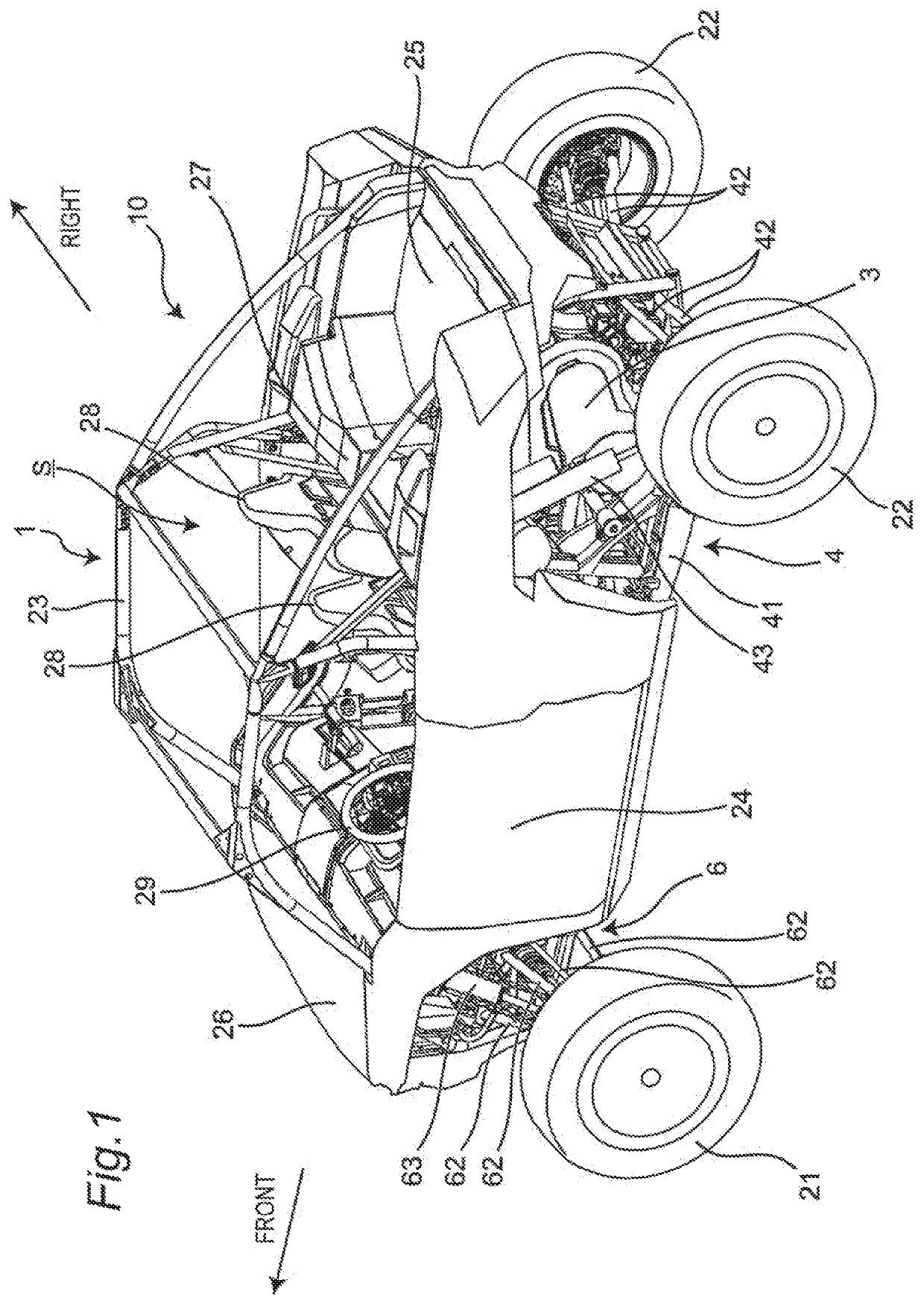
[0029]Hereinafter, a utility vehicle having an attaching structure for a stabilizer according to one embodiment of the present invention is described with reference to attached drawings. The utility vehicle is a vehicle for off-road traveling which travels not only on a grass field, a gravel field and a sandy field but also on an unpaved mountain road, a forest road, a muddy road, a rocky area or the like. For the sake of convenience of the description, an advancing direction of the utility vehicle is assumed as a “front side” of the utility vehicle and respective parts, and right and left sides in a vehicle width direction when an occupant riding on the utility vehicle faces forward are assumed as “right and left sides” of the utility vehicle and the respective parts.

[0030][Entire Structure of Vehicle]

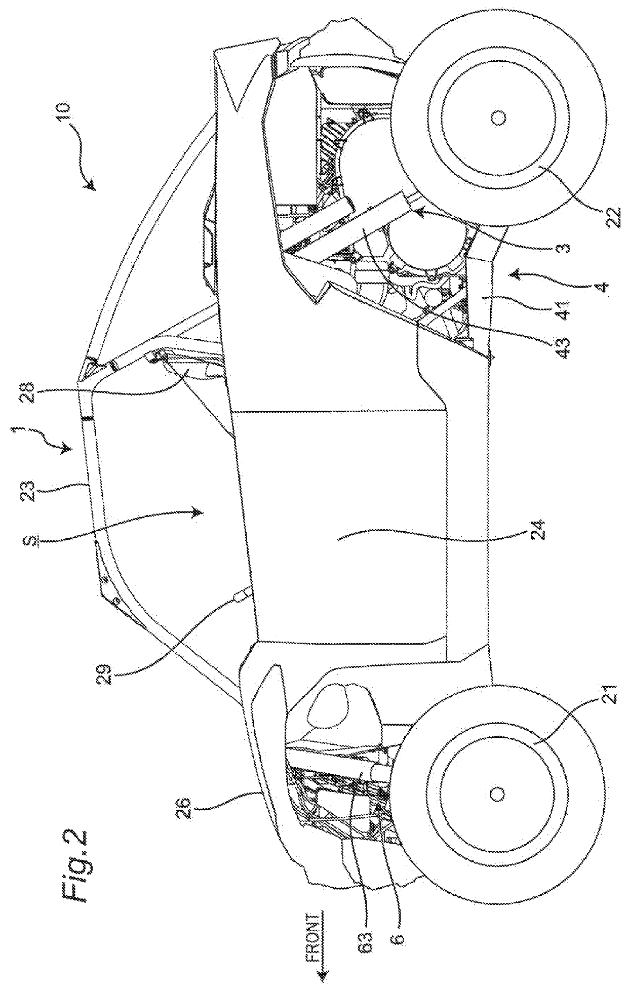
[0031]FIG. 1 is a perspective view of a utility vehicle which has an attaching structure for a stabilizer according to one embodiment of the present invention, and FIG. 2 is a left si...


PUM


Abstract

An attaching structure for a stabilizer of a utility vehicle includes: a pair of right and left independent suspension devices; the stabilizer which connects the pair of right and left independent suspension devices to each other; and a support member which is raised from a main frame and is configured to support a load from above. A through hole is defined in the support member such that the through hole penetrates the support member in a vehicle width direction, and the stabilizer passes through the through hole and is supported on the support member.

Description

BACKGROUND OF THE INVENTION1. Field of the Invention[0001]The present invention relates to an attaching structure for a stabilizer of a utility vehicle.2. Description of the Related Art[0002]Conventionally, as described in U.S. Pat. No. 8,746,719 specification, a stabilizer of a utility vehicle is supported by a bracket mounted on a vehicle body frame.SUMMARY OF THE INVENTION[0003]With such a configuration, when a large load is applied to a stabilizer from a suspension device, a case is considered where it is difficult to ensure a sufficient strength for supporting the stabilizer because of the structure of the bracket.[0004]Accordingly, it is an object of the present invention to provide an attaching structure for a stabilizer of a utility vehicle where a strength for supporting the stabilizer can be enhanced.[0005]To achieve the object of the present invention, there is provided an attaching structure for a stabilizer of a utility vehicle which includes:[0006]a pair of right and l...

Claims


Application Information

Patent Timeline
Patent Type & Authority Patents(United States)
IPC IPC(8): B60G21/02B60G7/00B60G3/14B62D23/00B60G7/02B60G21/055
CPCB60G3/14B60G7/02B60G21/026B60G21/0551B60G7/001B60G2300/07B60G2204/143B62D23/005B60G3/20B60G2200/144B62D25/088
Inventor HISAMURA, TAKASHINAKASHIMA, YUSUKE
Owner KAWASAKI MOTORS LTD
Why Eureka
Try Eureka