
Vane airfoil cooling air communication

a technology of air communication and airfoil, which is applied in the direction of engine fuction, machine/engine, stators, etc., can solve problems such as mechanical failure and corrosion

Active Publication Date: 2020-06-02
RTX CORP
View PDF9 Cites 1 Cited by
  • Summary
  • Abstract
  • Description
  • Claims
  • Application Information

AI Technical Summary

Benefits of technology

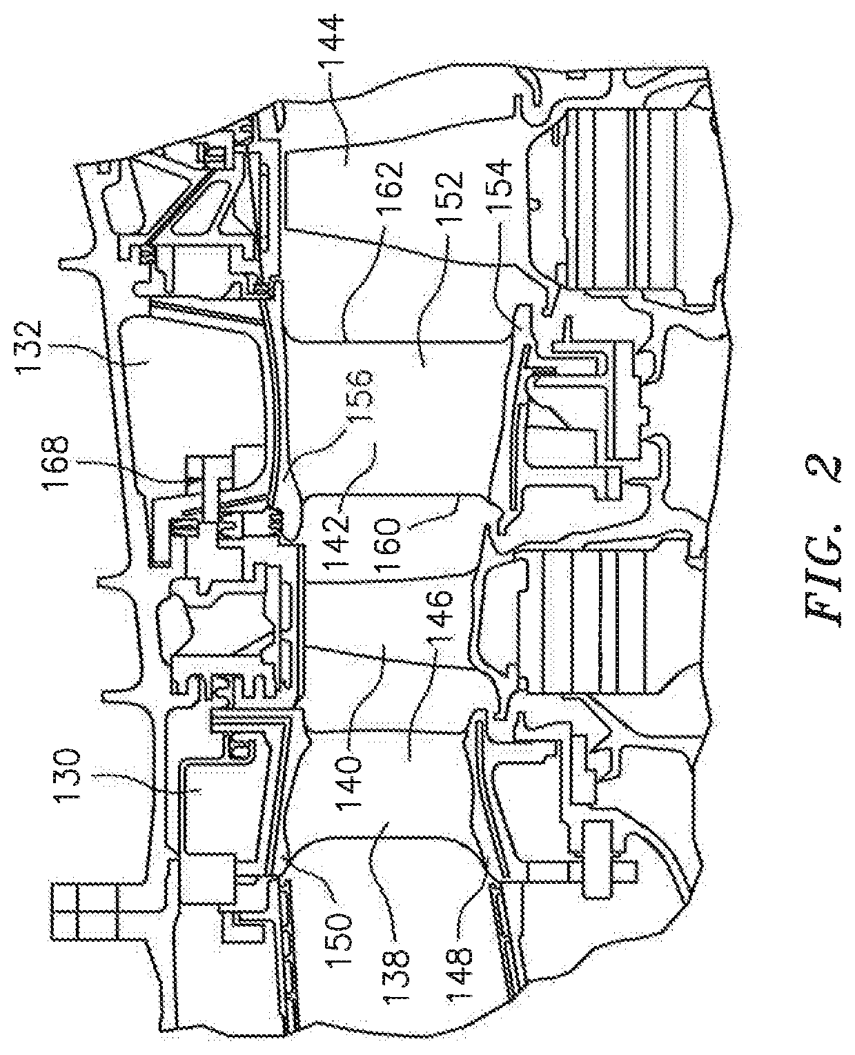
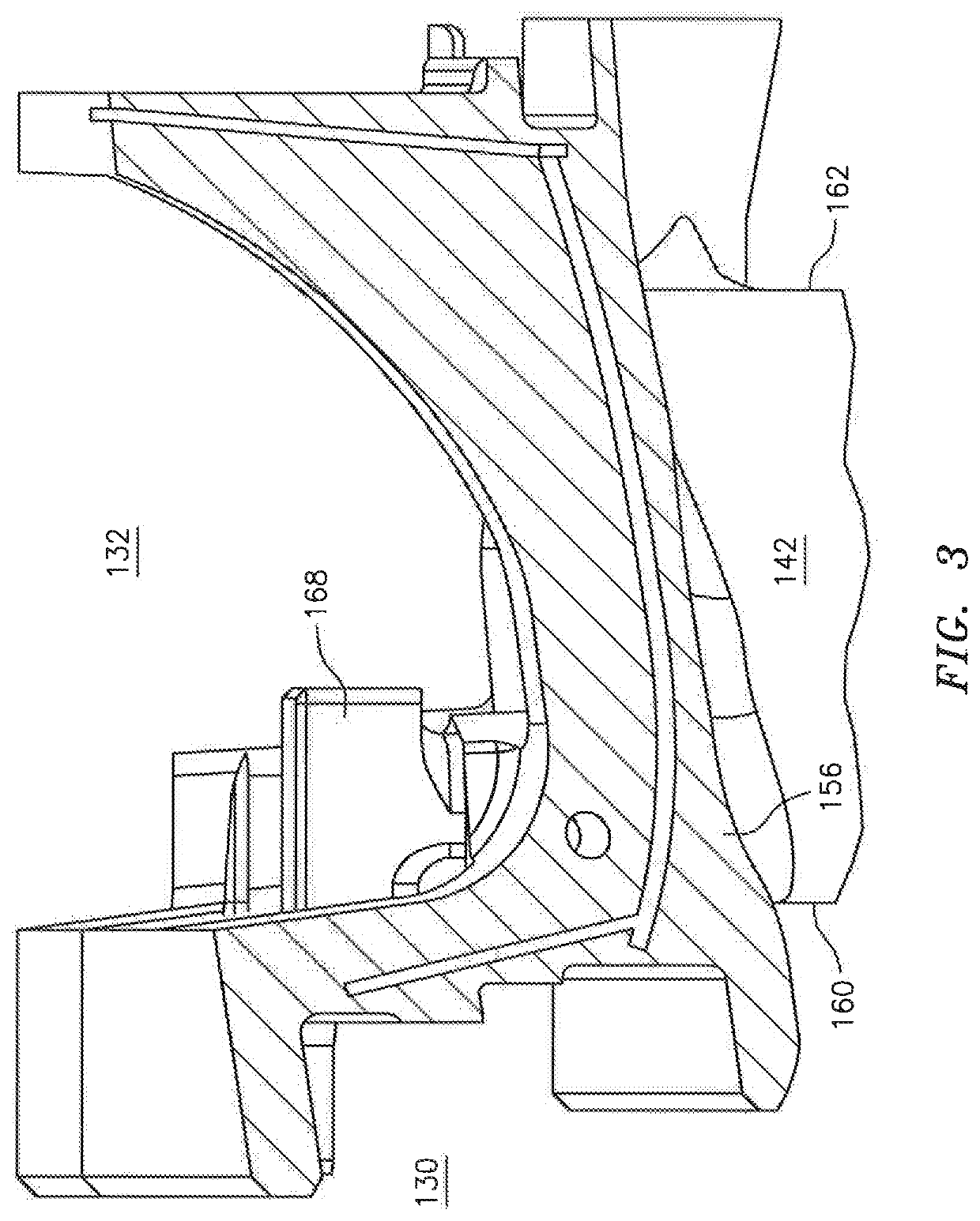
The patent describes a coolable airfoil for a gas turbine engine. The airfoil has a leading edge and a trailing edge and includes a suction side wall and a pressure side wall that form a cavity with cooling passages. The airfoil receives cooling air from a plenum formed between the outer platform and an engine case. The cooling air is directed to the cavity through a feed elbow. The technical effect of this design is to improve the cooling efficiency of the airfoil and to reduce the temperature of the airfoil components, which can improve the durability and reliability of the gas turbine engine.

Problems solved by technology

During engine operation the turbine blades and vanes are exposed to elevated temperatures that can lead to mechanical failure and corrosion.

Method used


Image

  • Vane airfoil cooling air communication
  • Vane airfoil cooling air communication
  • Vane airfoil cooling air communication

Examples


Embodiment Construction

[0030]It is noted that various connections are set forth between elements in the following description and in the drawings (the contents of which are incorporated in this specification by way of reference). It is noted that these connections are general and, unless specified otherwise, may be direct or indirect and that this specification is not Intended to be limiting in this respect. A coupling between two or more entities may refer to a direct connection or an indirect connection. An indirect connection may incorporate one or more intervening entities or a space / gap between the entities that are being coupled to one another.

[0031]Aspects of the disclosure may be applied in connection with a gas turbine engine.

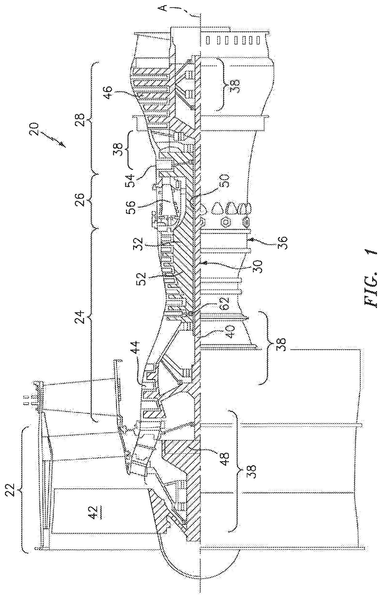
[0032]FIG. 1 schematically illustrates a gas turbine engine 20. The gas turbine engine 20 is disclosed herein as a two-spool turbo fan that generally incorporates a fan section 22, a compressor section 24, a combustor section 26 and a turbine section 28. Alternative engines ...


PUM


Abstract

A coolable airfoil for a gas turbine engine includes a suction side wall that extends from a leading edge to a trailing edge. A pressure side wall is joined to the suction side wall at the leading edge and the trailing edge and spaced from the suction side wall to form a cavity therein that includes a cooling circuit with a plurality of serpentine cooling passages. A cooling air inlet passage receives cooling air from a plenum formed between an outer platform and an engine case and routes the received cooling air from the plenum to the cooling circuit. The coolable airfoil may also include a cooling air feed elbow that includes a metering input orifice that receives compressor first discharge air that provides the received compressor first discharge air to a feed elbow cavity and is redirected via a feed elbow outlet passage to the cooling circuit.

Description

BACKGROUND OF THE INVENTION[0001]1. Technical Field[0002]The present disclosure relates to internally cooled turbomachinery components and, more particularly to providing cooling air to a vane.[0003]2. Background Information[0004]The blades and vanes used in the turbine section of a gas turbine engine each have an airfoil section that extends radially across an engine flowpath. During engine operation the turbine blades and vanes are exposed to elevated temperatures that can lead to mechanical failure and corrosion. Therefore, it is common practice to make the blades and vanes from a temperature tolerant alloy and to apply corrosion resistant and thermally insulating coatings to the airfoil and other flowpath exposed surfaces. It is also widespread practice to cool the airfoils by flowing a coolant through the interior of the airfoils.[0005]U.S. Pat. No. 5,827,043 assigned to the assignee of the present invention discloses that cooling air flows from a plenum to a cooling air inlet ...

Claims


Application Information

Patent Timeline
Patent Type & Authority Patents(United States)
IPC IPC(8): F01D25/12
CPCF01D25/12F05D2240/12F05D2220/32F05D2240/80F05D2260/201F01D5/187F01D9/065
Inventor ALLWOOD, THOMAS
Owner RTX CORP
Learn More