
Fuel cell device with a flushing gas path

a fuel cell and gas path technology, applied in the field of fuel cell devices with flushing gas paths, can solve the problems of limited installation space, complicated layout of fuel cell devices, and requiring additional installation spa

Active Publication Date: 2020-06-02
AUDI AG
View PDF31 Cites 0 Cited by
  • Summary
  • Abstract
  • Description
  • Claims
  • Application Information

AI Technical Summary

Benefits of technology

This configuration simplifies the fuel cell device structure, reduces installation space, and eliminates the need for separate components, enabling efficient hydrogen residue removal with minimal effort and energy consumption.

Problems solved by technology

However, these additional lines or other additional components of the flushing gas path complicate the layout of the fuel cell device and they require additional installation space.
However, precisely when the fuel cell device is intended for mobile use, for example, in an automobile, the installation space is limited.

Method used


Image

  • Fuel cell device with a flushing gas path
  • Fuel cell device with a flushing gas path

Examples


Embodiment Construction

[0023]The invention will be explained below by way of example on the basis of embodiments making reference to the accompanying drawings. The various features of the embodiments can be independently combined with each other, as was already explained in the individual advantageous embodiments.

[0024]First of all, the structure and function of a fuel cell device according to the invention are described with reference to the embodiment shown in FIG. 1.

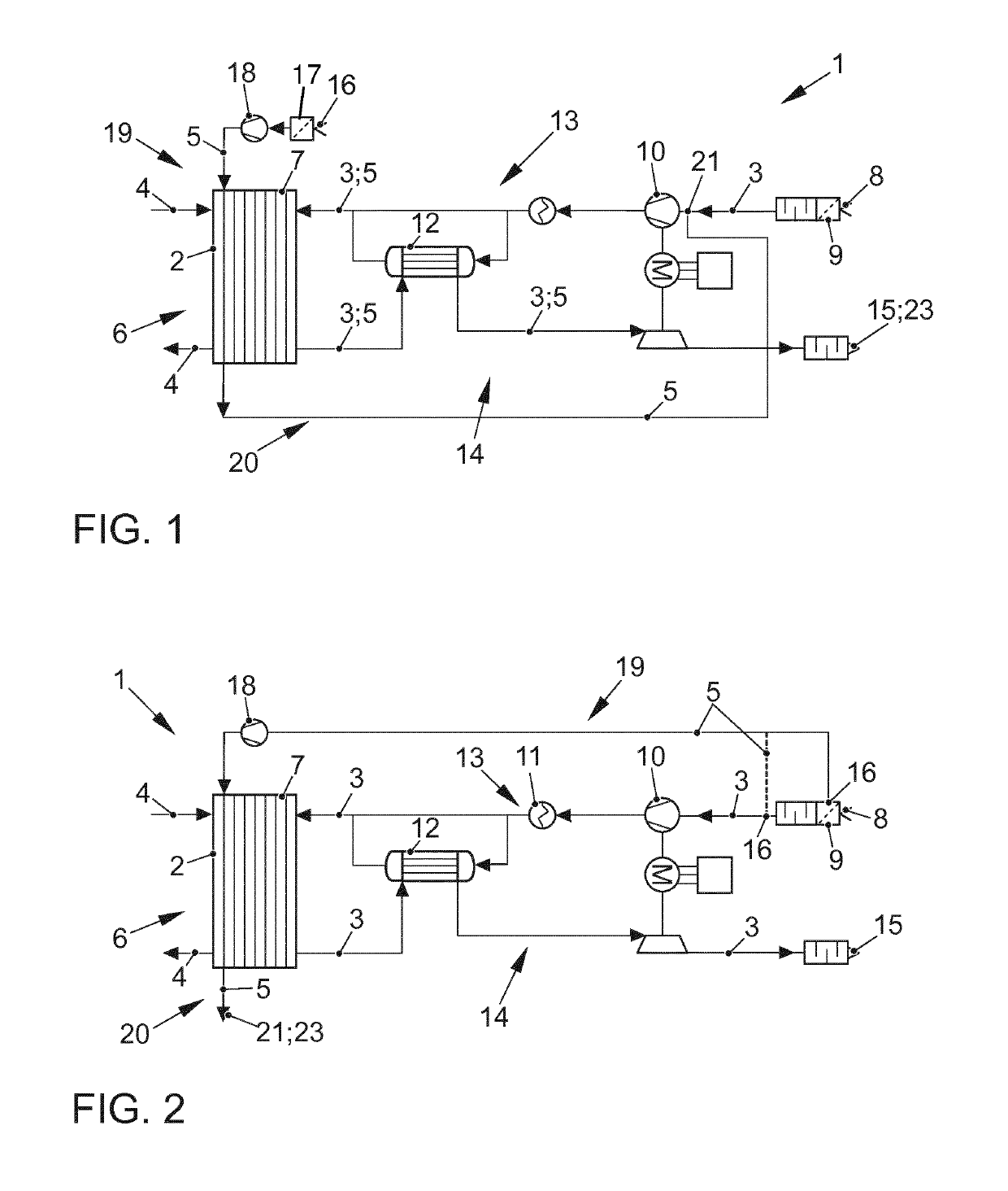
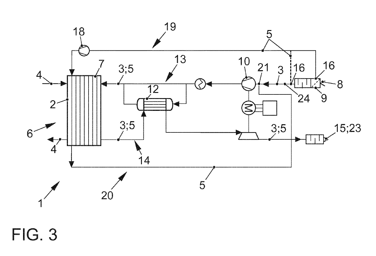
[0025]FIG. 1 schematically shows the fuel cell device 1 having a fuel cell 2, a cathode gas path 3, a section of an anode gas path 4, and a flushing gas path 5. The transport directions of the gas through the cathode gas path 3, the anode gas path 4, and the flushing gas path 5 are indicated by arrows.

[0026]The fuel cell 2 is configured with a membrane-electrode assembly 6 and a housing 7, whereby the membrane-electrode assembly 6 is arranged in the housing 7.

[0027]The cathode gas path 3 has an inlet 8 that can be configured, for example, a...


PUM

PropertyMeasurementUnit
pressureaaaaaaaaaa
surface areaaaaaaaaaaa

Abstract

A fuel cell device (1) having a fuel cell (2) with a housing (7) and, accommodated therein, a membrane-electrode assembly (6) with a cathode and an anode, having a cathode gas path (3) that serves to transport a cathode gas and that extends through the membrane-electrode assembly (6) on the cathode side, and having a flushing gas path (5) that serves to transport a flushing gas to flush the housing (7) during operation and that extends through the housing (7) is provided. It is provided that a section of the flushing gas path (5) runs through the cathode gas path (3). In this manner, the fuel cell device (1) has a compact structure of just a few parts.

Description

[0001]The invention relates to a fuel cell device having a fuel cell with a housing and, accommodated therein, a membrane-electrode assembly with a cathode and an anode, having a cathode gas path that serves to transport a cathode gas and that extends through the membrane-electrode assembly on the cathode side, and having a flushing gas path that serves to transport a flushing gas to flush the housing during operation and that extends through the housing.BACKGROUND[0002]Particularly when the fuel cell is operated with an anode gas containing hydrogen, it can be necessary to remove hydrogen from selected areas of the fuel cell device. For example, after switching off the fuel cell device, it can be necessary to flush the hydrogen out of the anode gas path in order to remove hydrogen residues. Such a fuel cell device is disclosed in the translation of the publication of international application DE 11 2008 000 254 T5. Moreover, it can be necessary to flush the housing that surrounds t...

Claims


Application Information

Patent Timeline
Patent Type & Authority Patents(United States)
IPC IPC(8): H01M8/04223H01M8/04119
CPCH01M8/04231H01M8/04179Y02T90/32H01M2250/20Y02E60/50Y02T90/40
Inventor GRUNDEI, DANIELBERGER, OLIVERKLEPPA, OLIVER
Owner AUDI AG
Learn More