Inductive power transfer apparatus

a technology of inductive power transfer and inductive power, which is applied in the direction of transformers/inductances magnetic cores, transformers/inductances coils/windings/connections, etc., can solve the problems of inability to provide power transfer, the height of the flux provided by the transformers/inductances beyond the pad, and the inability to provide the flux. the ground must have the same orientation as the pad under the ev or the effect of power transfer

Active Publication Date: 2020-06-02
AUCKLAND UNISERVICES LTD
View PDF14 Cites 1 Cited by
  • Summary
  • Abstract
  • Description
  • Claims
  • Application Information

AI Technical Summary

Benefits of technology

[0010]It is an object of the present invention to provide an inductive power transfer apparatus which may be able to overcome or at least ameliorate the above problems or at least will provide the public with a useful choice.
[0011]It is an alternative object of the invention to provide an inductive power transfer apparatus which will allow high flux usage and provide a low flux path length

Problems solved by technology

However, the useful flux that they can provide is relatively small, and the height, i.e. distance that they can provide flux beyond the pad, is likewise small.
The pads in the ground must have the same orientation as the pad under the EV or power transfer is not possible.
So these end fluxes produce no useful output.
This wasted flux adds to the pad's inductance, reduce its coupling factor, and cause losses in any metal pieces it comes in contact with under the car.
This removal is not very satisfactory and the pads have residual end flux that is very difficult to eliminate.
The solenoid pad can produce high useful flux patterns but they are less efficient as there are significant losses in the aluminium screens.

Method used


Image

  • Inductive power transfer apparatus
  • Inductive power transfer apparatus
  • Inductive power transfer apparatus

Examples


Embodiment Construction

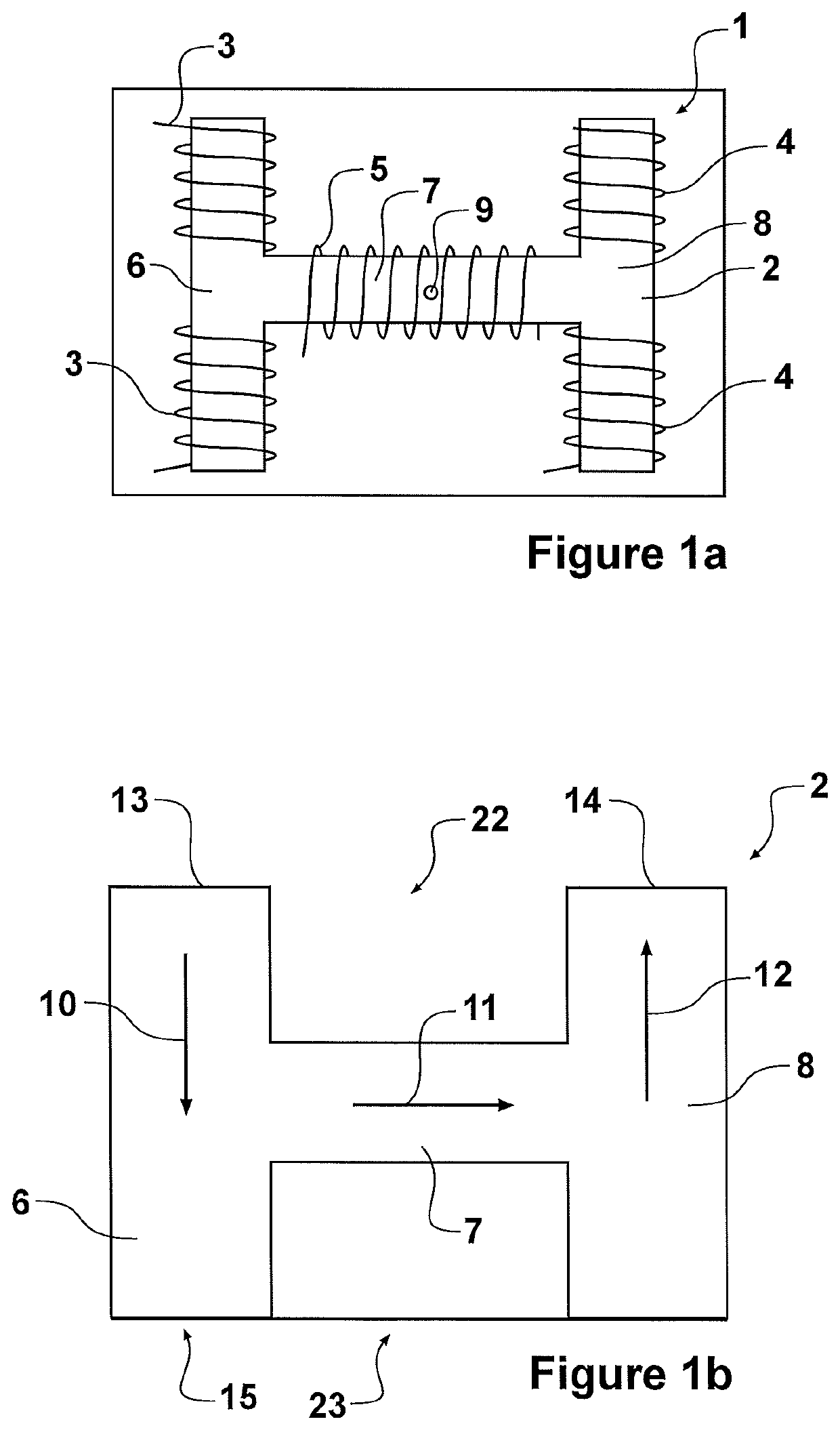
[0099]Referring first to FIG. 1a, a magnetic flux coupling device referred to herein as a pad 1 is shown in side view. As will be described in more detail further below, the pad 1 is adapted to guide or channel magnetic flux so that the pad provides a required magnetic field or flux pattern. One application of the apparatus described is for use in an inductive power transfer system.

[0100]In many IPT applications it is preferable to use a pad that is more extensive in two dimensions (for instance horizontally) than it is in a third dimension (height or depth). However, the term “pad” is used in this document to refer to any magnetic flux coupling (i.e. flux generating or receiving) structure, and is not limited to purely pad-like structures.

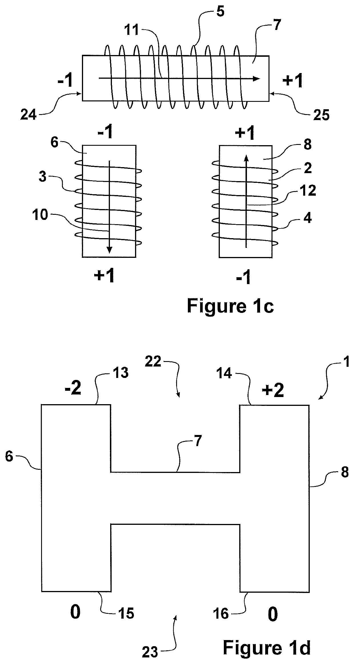
[0101]Referring to FIG. 1a, an H-shaped member 2 made of magnetically permeable material such as ferrite has three coils 3, 4, 5 which are magnetically associated with the member 2. The member 2 may be a unitary structure or may be made from separ...


PUM

PropertyMeasurementUnit
diameteraaaaaaaaaa
diameteraaaaaaaaaa
magnetic fieldaaaaaaaaaa

Abstract

An inductive power transfer apparatus may be used for producing or receiving a magnetic field for inductive power transfer. The apparatus has a central coil and two end coils, one of the end coils being provided at each end of the central coil. Some turns of each of the end coils are on one side of the central coil and the remaining turns are on the other side. The end coils act to weaken or cancel flux on one side of the central coil and guide magnetic flux through the central coil to provide an arch shaped flux pattern beyond the apparatus on the other side of the central coil.

Description

PRIORITY CLAIM TO RELATED APPLICATIONS[0001]This application is a U.S. national stage application filed under 35 U.S.C. § 371 from International Application Serial No. PCT / NZ2015 / 050087, which was filed 8 Jul. 2015, and published as WO2016 / 007023 on 14 Jan. 2016, and which claims priority to New Zealand Application No. 627210, filed 8 Jul. 2014, and which claims priority to New Zealand Application No. 706024, filed 17 Mar. 2015, and which claims priority to New Zealand Application No. 706620, filed 1 Apr. 2015, which applications and publication are incorporated by reference as if reproduced herein and made a part hereof in their entirety, and the benefit of priority of each of which is claimed herein.FIELD OF INVENTION[0002]The present invention relates to apparatus for producing magnetic flux from a source of electrical energy and / or receiving magnetic flux to provide a source of electrical energy. In one application the invention couples magnetic flux to provide an inductive powe...

Claims


Application Information

Patent Timeline
Patent Type & Authority Patents(United States)
IPC IPC(8): H02J50/12H01F38/14H01F27/38H02J50/10B60L53/12H01F27/24H01F27/28
CPCH01F27/38B60L53/12H01F38/14H01F27/28H01F27/24H02J50/10H02J50/12Y02T10/70Y02T10/7072Y02T90/14
Inventor BOYS, JOHN TALBOTCOVIC, GRANT ANTHONY
Owner AUCKLAND UNISERVICES LTD
Why Eureka
Try Eureka